Lecture 5 · Case Study: Nutshell Cache
Introduces how to start a verification task, complete Chisel-to-Verilog conversion, and verify Nutshell Cache requirements
The final task of the beginner course is to verify the Nutshell Cache using Toffee. After completing all the beginner tutorial materials, you need to submit a verification code repository and a verification report for the Nutshell Cache.
Starting a New Verification Task
With Toffee, you can already set up a complete verification environment and easily write test cases. However, in real-world work, you may often find it difficult to understand how to get started and ultimately complete a verification task. After actually writing code, you may encounter issues such as being unable to correctly divide Bundles, failing to correctly understand Agent high-level semantic encapsulation, and not knowing what to do after setting up the environment.
In this section, we will introduce how to complete a new verification task from scratch, and how to better use Toffee to complete verification tasks.
- Understand the Design Under Verification
When you receive a new design, you are often faced with dozens or hundreds of input and output signals. If you look at these signals directly, you may feel confused and not know where to start. At this point, you must believe that the input and output signals are all defined by the designer; as long as you understand the functionality of the design, you can understand the meaning of these signals.
If the designer provides a design document, you can read it to understand the design’s functionality, and then gradually map the functionality to the input and output signals. You should also clearly understand the timing of the input and output signals and how to use these signals to drive the design. Generally, you also need to read the design’s source code to find more detailed interface timing issues.
Once you have a general understanding of the DUT’s functionality and know how to drive the DUT interfaces, you can start setting up the verification environment.
- Divide Bundles
The first step in setting up the environment is to divide the interfaces into several interface sets based on their logical functionality. We can consider each interface set as a Bundle. Each divided Bundle should be independent and driven by a separate Agent.
However, the interfaces in actual practice often look like this:
|---------------------- DUT Bundle -------------------------------|

|------- Bundle 1 ------| |------ Bundle 2 ------| |-- Bundle 3 --|

|-- B1.1 --| |-- B1.2 --| |-- B2.1 --|
So the question arises: for example, should you create an Agent for each of B1.1 and B1.2 individually, or should you create a single Agent for Bundle 1?
This ultimately depends on the logical functionality of the interface. If you need to define an independent request that operates on both B1.1 and B1.2 simultaneously, then you should create an Agent for Bundle 1, rather than creating separate Agents for B1.1 and B1.2.
Even so, defining 1.2 for B1.1 and B1.2 is also feasible. This increases the granularity of Agent division, but sacrifices operational continuity, making upper-level code and reference model writing more complex. Therefore, choosing the right division granularity requires a trade-off based on specific business needs. In the final division, all Agents together should be able to cover all interfaces of the DUT Bundle.
In practice, to facilitate DUT connection, you can define a DUT Bundle that connects all interfaces at once, and the Env distributes the sub-Bundles to each Agent.
- Write Agents
Once the Bundle division is complete, you can start writing Agents to drive these Bundles. You need to write an Agent for each Bundle.
First, you can start by writing drive methods. Drive methods are actually a high-level semantic encapsulation of a Bundle, so the high-level semantic information should carry all the information needed to drive the Bundle. If a signal in the Bundle requires a value but the parameters do not provide information related to that signal, then this high-level semantic encapsulation is incomplete. You should try to avoid assuming values for certain signals in drive methods. If you make assumptions about a signal in the Agent, the DUT’s output will be affected by this assumption, which may cause the reference model and DUT behavior to be inconsistent.
At the same time, this high-level encapsulation also determines the functional level of the reference model. The reference model will directly interact with high-level semantic information and will not involve underlying signals.
If the reference model needs to be written in a function call pattern, then the DUT’s output should be returned via function return values. If the reference model needs to be written in an independent execution flow pattern, then you should write monitoring methods to convert all DUT outputs into high-level semantic information and output them through monitoring methods.
- Encapsulate into Env
Once all Agents are written, or after selecting some existing Agents, you can encapsulate these Agents into an Env.
The Env encapsulates the entire verification environment and establishes the reference model writing specifications.
- Write Reference Model
There is no need to wait until the Env is fully written before starting to write the reference model. It can be done simultaneously with Agent writing, and you can write some drive code in real time to verify the correctness. Of course, if the Agent writing is particularly standardized, it is also feasible to write the reference model after completing the full Env.
The most important thing for the reference model is choosing the right writing pattern. Both function call pattern and independent execution flow pattern are feasible, but in different scenarios, choosing different patterns will be more convenient.
- Determine Functional Points and Test Points
After writing the Env and reference model, you cannot start writing test cases immediately, because at this point there is no direction for test case writing. Writing test cases blindly will not allow the design under test to be fully verified.
💡For the organization of functional points and test points, you can refer to Lecture 1 · In-Depth Analysis: Organization of Functional Points and Test Points.
- Write Test Cases
Once the functional points and test points list is determined, you can start writing test cases. A test case needs to be able to cover one or more test points to verify whether the functional points are correct. All test cases should be able to cover all test points (100% functional coverage) and cover all design lines (100% line coverage), so as to ensure the completeness of verification.
How to ensure the correctness of verification? If using the reference model comparison method, when the comparison fails, Toffee will automatically throw an exception to make the test case fail. If using the direct comparison method, you should use assert in the test case to write comparison code, and when the comparison fails, the test case will also fail. Ultimately, when all test cases pass, it means the functionality has been verified as correct.
During the writing process, you need to use the interfaces provided in Env to drive the DUT. If there is a situation where multiple drive methods need to interact, you can use Executor to encapsulate higher-level functions. In other words, the interaction at the drive method level is completed during the writing of test cases.
- Write Verification Report
Once both line coverage and functional coverage reach 100%, the verification is complete. Finally, you need to write a verification report to summarize the results of the verification task. If issues are found in the design under test, the reasons should also be described in detail in the verification report. If line coverage or functional coverage does not reach 100%, the reasons should also be explained in the verification report. The format of the report should follow the company’s unified internal specifications.
Generating the Nutshell Cache DUT
Nutshell Cache
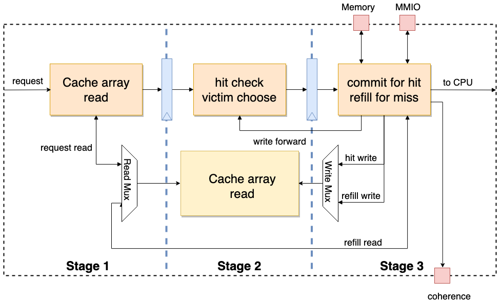
Nutshell Cache is the cache module used in the Nutshell processor. It adopts a three-stage pipeline design. When the third stage detects that the current request is an MMIO or a refill occurs, the pipeline will be stalled. At the same time, Nutshell Cache adopts a customizable modular design. By changing parameters, it can generate L1 Cache or L2 Cache with different storage sizes. Additionally, Nutshell Cache has a coherence interface and can handle coherence-related requests.
Chisel and Nutshell
Accurately speaking, Chisel is a high-level hardware construction language (HCL) based on the Scala language. Traditional HDLs describe circuits, while HCLs generate circuits, making them more abstract and high-level. The Stage package in Chisel can convert HCL designs into traditional HDL language designs such as Verilog and System Verilog. Combined with tools like Mill and Sbt for Scala, automated development can be achieved.
💡If you are not familiar with the Chisel language, you can first browse the first three chapters of the Chisel Bootcamp to quickly familiarize yourself with Chisel syntax.
Nutshell is a modular design implemented in Chisel, based on the RISC-V RV64 open instruction set, with a single-issue in-order processor. For a more detailed introduction to Nutshell, please refer to: https://oscpu.github.io/NutShell-doc/
Chisel to Verilog
The stage library in Chisel can help convert Chisel code into traditional HDL code such as Verilog and System Verilog. Below, we will briefly introduce how to convert a Chisel-based cache implementation into the corresponding Verilog circuit description.
Please first ensure that the JDK environment is configured!
⚠️Warning: JDK version ≥21 will cause compilation errors!
The example operations in this tutorial are all performed in the cache-ut directory:
mkdir cache-ut
cd cache-ut
Configure Mill
Execute the following command in the cache-ut directory:
curl -L https://github.com/com-lihaoyi/mill/releases/download/0.11.13/0.11.13 > mill && chmod +x mill
echo 0.11.13 > .mill-version
⚠️Warning: Mill versions higher than
0.11.xmay cause failures.
If executing ./mill --version includes:
Mill Build Tool version 0.11.13
It means Mill has been configured successfully.
Initialize Nutshell Environment
Go back to the cache-ut folder, then download the entire Nutshell source code from the source repository and initialize it:
git clone https://github.com/OSCPU/NutShell.git
cd NutShell && git checkout 97a025d
make init
Create Scala Build Configuration
Create build.sc in the cache-ut directory with the following content:
import $file.NutShell.build
import mill._, scalalib._
import coursier.maven.MavenRepository
import mill.scalalib.TestModule._

// Specify Nutshell dependencies
object difftest extends NutShell.build.CommonNS {
  override def millSourcePath = os.pwd / "NutShell" / "difftest"
}

// Nutshell configuration
object NtShell extends NutShell.build.CommonNS with NutShell.build.HasChiselTests {
  override def millSourcePath = os.pwd / "NutShell"
  override def moduleDeps = super.moduleDeps ++ Seq(
        difftest,
  )
}

// UT environment configuration
object ut extends NutShell.build.CommonNS with ScalaTest{
    override def millSourcePath = os.pwd
    override def moduleDeps = super.moduleDeps ++ Seq(
        NtShell
    )
}
Instantiate Cache
After creating the configuration information, according to Scala conventions, create the source code directory src/main/scala in the cache-ut directory.
Then, you can create src/main/scala/nut_cache.scala in the cache-ut directory and use the following code to instantiate Cache and convert it to Verilog code:
package ut_nutshell

import chisel3._
import chisel3.util._
import nutcore._
import top._
import chisel3.stage._

object CacheMain extends App {
  (new ChiselStage).execute(args, Seq(
      ChiselGeneratorAnnotation(() => new Cache()(CacheConfig(ro = false, name = "tcache", userBits = 16)))
    ))
}
Generate RTL
After completing the creation of all the above files, execute the following command in the cache-ut directory:
mkdir build
./mill --no-server -d ut.runMain ut_nutshell.CacheMain --target-dir build --output-file Cache
After the above command executes successfully, a Verilog file Cache.v will be generated in the build directory.
After that, you can use the Picker tool to convert Cache.v to a Python module. Except for Chisel, almost all other HCL languages can generate corresponding RTL code, so the basic process above also applies to other HCLs.
Verifying Nutshell Cache
After learning the aforementioned knowledge, I believe you have a certain understanding of hardware verification methods. Please do a practical exercise! Please verify the Nutshell Cache, write verification code and a test report, and submit the verification report and code to the GitHub Discussion board on UnityChipForXiangShan. The report content should include functional analysis, test point decomposition, test case writing, verification results analysis, and verification conclusions.
The format of the verification report can be referenced from the previous Nutshell Cache Verification Case to complete your verification.
Before starting verification, it is recommended to read through the Picker and Toffee documentation.
For the Nutshell Cache task, please refer to: Learning Task 3: Verify Nutshell Cache
- Understand the Design Under Verification
After receiving a new design, you often face dozens or hundreds of input/output signals. If you look at these signals directly, you may feel confused and not know where to start. At this point, you must believe that input/output signals are all defined by the designer. As long as you can understand the functionality of the design, you can understand the meaning of these signals.
If the designer provides a design document, you can read it to understand the design’s functionality, and gradually map the functionality to the input/output signals. You should also clearly understand the timing of the input/output signals and how to use these signals to drive the design. Generally, you also need to read the design’s source code to find more detailed interface timing issues.
Once you have a general understanding of the DUT’s functionality and know how to drive the DUT interfaces, you can start setting up the verification environment.
- Dividing Bundles
The first step in setting up the environment is to divide the interfaces into several interface sets based on their logical functionality. We can treat each interface set as a Bundle. Each divided Bundle should be independent and driven by a separate Agent.
However, interfaces in practice often look like this:
|---------------------- DUT Bundle -------------------------------|

|------- Bundle 1 ------| |------ Bundle 2 ------| |-- Bundle 3 --|

|-- B1.1 --| |-- B1.2 --| |-- B2.1 --|
Then the question arises: for example, should you create an Agent for each of B1.1 and B1.2, or should you directly create an Agent for Bundle 1?
This ultimately depends on the logical functionality of the interfaces. If you need to define an independent request that operates on both B1.1 and B1.2 simultaneously, then you should create an Agent for Bundle 1, rather than creating separate Agents for B1.1 and B1.2.
Even so, it is also feasible to define separate Agents for B1.1 and B1.2. This increases the granularity of Agent division but sacrifices the continuity of operations, making upper-level code and reference model writing more complex. Therefore, choosing the appropriate division granularity requires a trade-off based on specific business needs. In the final division, all Agents together should cover all interfaces of the DUT Bundle.
In practice, to facilitate DUT connection, you can define a DUT Bundle that connects all interfaces at once, and have the Env distribute the sub-Bundles to various Agents.
- Writing Agents
Once the Bundle division is complete, you can start writing Agents to drive these Bundles. You need to write an Agent for each Bundle.
First, you can start by writing drive methods. Drive methods are actually a high-level semantic encapsulation of a Bundle. Therefore, the high-level semantic information should carry all the information needed to drive the Bundle. If a signal in the Bundle requires a value but the parameters do not provide information related to that signal, then this high-level semantic encapsulation is incomplete. You should avoid making assumptions about signal values in drive methods. If you assume a signal’s value in the Agent, the DUT’s output will be affected by this assumption, which may cause the reference model’s behavior to be inconsistent with the DUT’s behavior.
At the same time, this high-level encapsulation also determines the functional level of the reference model. The reference model will directly interact with high-level semantic information and will not involve the underlying signals.
If the reference model needs to be written using a function call pattern, the DUT’s output should be returned through the function’s return value. If the reference model needs to be written using an independent execution flow pattern, you should write monitoring methods to convert all DUT outputs into high-level semantic information and output them through the monitoring methods.
- Encapsulating into Env
Once all Agents are written, or after selecting existing Agents, you can encapsulate these Agents into an Env.
The Env encapsulates the entire verification environment and establishes the specification for the reference model’s writing.
- Writing the Reference Model
There is no need to wait until the Env is complete to start writing the reference model. It can be written simultaneously with Agent writing, and you can write some drive code in real-time to verify the correctness of the writing. Of course, if the Agent writing is particularly standardized, it is also feasible to write the reference model after completing the full Env.
The most important aspect of the reference model is choosing the appropriate writing pattern. Both the function call pattern and the independent execution flow pattern are viable, but choosing different patterns in different scenarios will be more convenient.
- Determining Functional Points and Test Points
After writing the Env and reference model, you cannot directly start writing test cases, because at this point there is no direction for writing test cases. Blindly writing test cases cannot fully verify the design under test.
💡For the organization of functional points and test points, you can refer to Lecture 1 · In-Depth Analysis: Organization of Functional Points and Test Points.
- Writing Test Cases
Once the list of functional points and test points is determined, you can start writing test cases. A test case needs to cover one or more test points to verify whether the functional points are correct. All test cases should cover all test points (100% functional coverage) and cover all design lines (100% line coverage), so as to ensure the completeness of verification.
How do you ensure the correctness of verification? If using the reference model comparison method, when comparison fails, Toffee will automatically throw an exception, causing the test case to fail. If using the direct comparison method, you should use assert in test cases to write comparison code. When comparison fails, the test case will also fail. Ultimately, when all test cases pass, it means the functionality has been verified as correct.
During the writing process, you need to use the interfaces provided by Env to drive the DUT. If there are situations requiring interaction between multiple drive methods, you can use Executor to encapsulate higher-level functions. That is to say, interaction at the drive method level is completed in the writing of test cases.
- Writing the Verification Report
When both line coverage and functional coverage reach 100%, the verification is complete. Finally, you need to write a verification report to summarize the results of the verification task. If any problems are found in the design under test during verification, the causes should also be described in detail in the verification report. If line coverage or functional coverage does not reach 100%, the reasons should also be explained in the verification report. The report format should follow the company’s internal unified standards.
Generating the Nutshell Cache DUT
Nutshell Cache
Nutshell Cache is the cache module used in the Nutshell processor. It adopts a three-stage pipeline design. When the third stage detects that the current request is MMIO or a refill occurs, the pipeline is stalled. At the same time, Nutshell Cache adopts a customizable modular design. By changing parameters, it can generate L1 Cache or L2 Cache with different storage sizes. In addition, Nutshell Cache has a coherence interface and can handle coherence-related requests.
Chisel and Nutshell
Accurately speaking, Chisel is a high-level hardware construction language (HCL) based on Scala. Traditional HDL describes circuits, while HCL generates circuits, being more abstract and advanced. The Stage package in Chisel can convert HCL designs into traditional HDL language designs such as Verilog and System Verilog. Together with Scala tools like Mill and Sbt, automated development can be achieved.
💡If you are not familiar with Chisel language, you can first browse the first three chapters of Chisel Bootcamp to quickly familiarize yourself with Chisel syntax.
Nutshell is a sequential single-issue processor implementation based on the RISC-V RV64 open instruction set, modularly designed using Chisel language. For a more detailed introduction to Nutshell, please refer to: https://oscpu.github.io/NutShell-doc/
Chisel to Verilog
The stage library in Chisel can help generate traditional HDL code such as Verilog and System Verilog from Chisel code. Below, we will briefly introduce how to convert a Chisel-based cache implementation into the corresponding Verilog circuit description.
Please first ensure the JDK environment is configured!
⚠️Warning: JDK version ≥21 will cause compilation errors!
The example operations in this tutorial are all performed in the cache-ut directory:
mkdir cache-ut
cd cache-ut
Configuring Mill
Execute the following command in the cache-ut directory:
curl -L https://github.com/com-lihaoyi/mill/releases/download/0.11.13/0.11.13 > mill && chmod +x mill
echo 0.11.13 > .mill-version
⚠️Warning: Mill versions higher than
0.11.xmay cause failures
If executing ./mill --version contains:
Mill Build Tool version 0.11.13
It means Mill is configured.
Initializing the Nutshell Environment
Go back to the cache-ut folder, then download the entire Nutshell source code from the source repository and initialize it:
git clone https://github.com/OSCPU/NutShell.git
cd NutShell && git checkout 97a025d
make init
Creating the Scala Build Configuration
Create build.sc in the cache-ut directory with the following content:
import $file.NutShell.build
import mill._, scalalib._
import coursier.maven.MavenRepository
import mill.scalalib.TestModule._

// Specify Nutshell dependencies
object difftest extends NutShell.build.CommonNS {
  override def millSourcePath = os.pwd / "NutShell" / "difftest"
}

// Nutshell configuration
object NtShell extends NutShell.build.CommonNS with NutShell.build.HasChiselTests {
  override def millSourcePath = os.pwd / "NutShell"
  override def moduleDeps = super.moduleDeps ++ Seq(
        difftest,
  )
}

// UT environment configuration
object ut extends NutShell.build.CommonNS with ScalaTest{
    override def millSourcePath = os.pwd
    override def moduleDeps = super.moduleDeps ++ Seq(
        NtShell
    )
}
Instantiating Cache
After creating the configuration, according to Scala conventions, create the src/main/scala source code directory in the cache-ut directory.
Then, you can create src/main/scala/nut_cache.scala in the cache-ut directory, and use the following code to instantiate Cache and convert it to Verilog:
package ut_nutshell

import chisel3._
import chisel3.util._
import nutcore._
import top._
import chisel3.stage._

object CacheMain extends App {
  (new ChiselStage).execute(args, Seq(
      ChiselGeneratorAnnotation(() => new Cache()(CacheConfig(ro = false, name = "tcache", userBits = 16)))
    ))
}
Generating RTL
After completing all the above files, execute the following command in the cache-ut directory:
mkdir build
./mill --no-server -d ut.runMain ut_nutshell.CacheMain --target-dir build --output-file Cache
After the above command executes successfully, the verilog file Cache.v will be generated in the build directory.
Then you can use the picker tool to convert Cache.v to a Python module. Besides Chisel, almost all other HCL languages can generate corresponding RTL code, so the above basic process also applies to other HCL.
Verifying Nutshell Cache
After learning the preceding knowledge, I believe you have a certain understanding of hardware verification methods. Please do a hands-on exercise! Please verify Nutshell Cache, write verification code and a test report, and submit the verification report and code in the UnityChipForXiangShan’s GitHub discussion section. The report content should include functional analysis, test point decomposition, test case writing, verification result analysis, and verification conclusions.
The format of the verification report can be completed by referring to the previous Nutshell Cache Verification Case.
Before starting verification, it is recommended to first read through the picker and Toffee documentation
For Nutshell Cache task, please refer to: Learning Task 3: Verify Nutshell Cache