Lecture 4·Advanced Case: Dual-Port Stack
Introduction
After completing the first three lectures, we have mastered the fundamental concepts of chip verification (Lecture 1), learned how to use the Picker tool to generate and basically operate the DUT (Lecture 2), and briefly touched upon the Toffee verification framework and its core asynchronous programming philosophy (Lecture 3). This lecture will enter an advanced application case, aiming to apply the previously learned knowledge to a scenario closer to actual engineering complexity.
The core objective of this lecture is to learn and demonstrate how to handle the verification of concurrent interfaces under the premise of only using picker, which is a common and important challenge in chip verification. We will take a dual-port stack as an example, a design that allows two ports to perform independent read and write operations simultaneously.
To address this concurrency, we will explore and practice two different driving methods:
State Machine based on Callback Functions: A traditional way of handling concurrent events.
Asynchronous Driving based on Coroutines: Utilizing the asynchronous interfaces provided by Picker and Python’s built-in
asynciolibrary. This method directly applies the principles of asynchronous programming introduced in Lecture 3 withasync/await.
By comparing these two methods, you will be able to more deeply understand:
Different strategies and their pros and cons for handling concurrent verification problems.
The advantages of the asynchronous programming model (such as
async/awaitand coroutines) over traditional callback functions in simplifying concurrent logic and avoiding complex state machines.Although this example does not use the complete Toffee framework, the coroutine method it demonstrates is the core foundation of modern verification frameworks like Toffee. Understanding it is a crucial step towards mastering Toffee.
How to apply the basic tools (Picker) and programming concepts (asynchronous) learned in previous lectures to solve specific and challenging verification problems.
Introduction to Dual-Port Stack
A dual-port stack is a data structure that supports concurrent operations from two ports. Compared to traditional single-port stacks, a dual-port stack allows simultaneous data read and write operations. In scenarios such as multi-threaded concurrent read/write, a dual-port stack can provide better performance. In this example, we provide a simple implementation of a dual-port stack, and its source code is as follows:
// dual_port_stack.v
module dual_port_stack (
    input clk,            // Clock signal
    input rst,            // Asynchronous reset signal

    // Interface 0
    input in0_valid,      // Input valid signal for interface 0
    output in0_ready,     // Module ready signal for interface 0
    input [7:0] in0_data, // Input data for interface 0
    input [1:0] in0_cmd,  // Command for interface 0 (PUSH or POP)
    output out0_valid,    // Output valid signal for interface 0
    input out0_ready,     // Receiving end ready to accept output data for interface 0
    output [7:0] out0_data, // Output data for interface 0
    output [1:0] out0_cmd,  // Command feedback for interface 0 (PUSH_OKAY or POP_OKAY)

    // Interface 1
    input in1_valid,      // Input valid signal for interface 1
    output in1_ready,     // Module ready signal for interface 1
    input [7:0] in1_data, // Input data for interface 1
    input [1:0] in1_cmd,  // Command for interface 1 (PUSH or POP)
    output out1_valid,    // Output valid signal for interface 1
    input out1_ready,     // Receiving end ready to accept output data for interface 1
    output [7:0] out1_data, // Output data for interface 1
    output [1:0] out1_cmd   // Command feedback for interface 1 (PUSH_OKAY or POP_OKAY)
);

    // Command definitions
    localparam CMD_PUSH     = 2'b00; // Push
    localparam CMD_POP      = 2'b01; // Pop
    localparam CMD_PUSH_OKAY = 2'b10; // Push acknowledge
    localparam CMD_POP_OKAY  = 2'b11; // Pop acknowledge

    // Stack memory (256 bytes) and stack pointer
    reg [7:0] stack_mem[0:255]; // Stack memory
    reg [7:0] sp;               // Stack pointer, pointing to the next empty slot
    reg busy;                   // Busy state to prevent simultaneous operations from both ports

    // Output registers, separately for interface 0 and interface 1
    reg [7:0] out0_data_reg, out1_data_reg;
    reg [1:0] out0_cmd_reg, out1_cmd_reg;
    reg out0_valid_reg, out1_valid_reg;

    // Connect registers to output ports
    assign out0_data = out0_data_reg;
    assign out0_cmd = out0_cmd_reg;
    assign out0_valid = out0_valid_reg;
    assign out1_data = out1_data_reg;
    assign out1_cmd = out1_cmd_reg;
    assign out1_valid = out1_valid_reg;

    // Main logic block
    always @(posedge clk or posedge rst) begin
        if (rst) begin
            // Reset: clear stack pointer and busy state
            sp <= 0;
            busy <= 0;
        end else begin
            // Interface 0 command processing
            if (!busy && in0_valid && in0_ready) begin
                case (in0_cmd)
                    CMD_PUSH: begin                   // PUSH command
                        busy <= 1;                    // Set busy flag
                        sp <= sp + 1;                 // Increment stack pointer
                        stack_mem[sp] <= in0_data;    // Push data
                        out0_valid_reg <= 1;          // Output valid signal
                        out0_cmd_reg <= CMD_PUSH_OKAY;// Return command acknowledge
                    end
                    CMD_POP: begin                          // POP command
                        busy <= 1;                          // Set busy flag
                        sp <= sp - 1;                       // Decrement stack pointer
                        out0_data_reg <= stack_mem[sp - 1]; // Output data
                        out0_valid_reg <= 1;
                        out0_cmd_reg <= CMD_POP_OKAY;
                    end
                    default: begin
                        out0_valid_reg <= 0; // Ignore illegal commands
                    end
                endcase
            end

            // Interface 1 command processing (if not preempted by interface 0)
            if (!busy && in1_valid && in1_ready) begin
                case (in1_cmd)
                    CMD_PUSH: begin
                        busy <= 1;
                        sp <= sp + 1;
                        stack_mem[sp] <= in1_data;
                        out1_valid_reg <= 1;
                        out1_cmd_reg <= CMD_PUSH_OKAY;
                    end
                    CMD_POP: begin
                        busy <= 1;
                        sp <= sp - 1;
                        out1_data_reg <= stack_mem[sp - 1];
                        out1_valid_reg <= 1;
                        out1_cmd_reg <= CMD_POP_OKAY;
                    end
                    default: begin
                        out1_valid_reg <= 0;
                    end
                endcase
            end

            // Interface 0 response complete, clear busy and valid
            if (busy && out0_ready) begin
                out0_valid_reg <= 0;
                busy <= 0;
            end

            // Interface 1 response complete, clear busy and valid
            if (busy && out1_ready) begin
                out1_valid_reg <= 0;
                busy <= 0;
            end
        end
    end

    // Interface 0 ready condition: stack not full (PUSH) or not empty (POP), and not busy
    assign in0_ready = (in0_cmd == CMD_PUSH && sp < 255 || in0_cmd == CMD_POP && sp > 0) && !busy;

    // Interface 1 ready condition: same as above, but interface 0 takes priority if also valid and ready
    assign in1_ready = (in1_cmd == CMD_PUSH && sp < 255 || in1_cmd == CMD_POP && sp > 0) && !busy && !(in0_ready && in0_valid);

endmodule
Port Description
Besides the clock and reset signals, each port of the dual-port stack has the following signals:
Request Port
| Signal | Meaning | Direction |
|---|---|---|
| in_valid | External request input valid: indicates in_cmd and in_data are valid | input |
| in_cmd | External request input command: 00 for PUSH, 01 for POP | input |
| in_data | External request input data: data to write to the stack (useful only during PUSH) | input |
| in_ready | Stack is ready to receive request: (Output by the stack module) | output |
Response Port
| Signal | Meaning | Direction |
|---|---|---|
| out_valid | Stack response output valid: output data/command is valid (POP successful or PUSH completed) | output |
| out_cmd | Stack response output command: 10 indicates PUSH_OKAY, 11 indicates POP_OKAY | output |
| out_data | Stack response output data: data popped from top of stack when request command is POP | output |
| out_ready | External device is ready to receive response: (Input by external device) | input |
💡 Note: The dual-port stack has two interfaces, and the real signal names are like
inx_valid,outx_cmd, etc., where x is 0 or 1 depending on the port number. For example,in0_validindicates the external request valid signal for port 0.
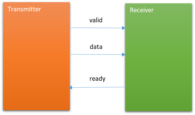
Handshake Protocol
You might wonder, intuitively, a request port only needs to initiate a request via input signals, and a response port only needs to read output signals. But why do they both simultaneously require input and output signals for control? Here we have to introduce a concept: Handshake Protocol.
What is Handshake Protocol
The dual-port stack dual_port_stack module uses a typical “valid-ready” handshake protocol.
The core purpose of the handshake protocol existing is to securely, reliably, and flexibly transmit data between different modules, especially in hardware, where different modules may operate at different clock rhythms, processing capabilities, or might simply not be synchronous at all times.
The above sentence is quite abstract. Please imagine the following two situations below:
- If the sender sends data directly but the receiver is not yet ready, then even if the data is transmitted, the receiver won’t have time to perform any effective processing, and the sender will likely not send this data again, meaning this data is effectively lost.
- In another situation, if the sender sends invalid data, it is obvious that the receiver does not need to perform any processing on it.
To avoid these two situations, we stipulate:
The input data can only be transmitted successfully when the sender has prepared valid data and the receiver is ready to receive data, meaning:
if (valid && ready) then transmit data. This is the core of the valid-ready handshake protocol~
Handshake Signals
valid: Determined by the sender (output by sender), informs the other party that the signal it wants to transmit is valid (input to receiver).ready: Determined by the receiver (output by receiver), informs the sender that it is prepared to receive the signal (input to sender).data: The data the sender wants to transmit to the receiver.
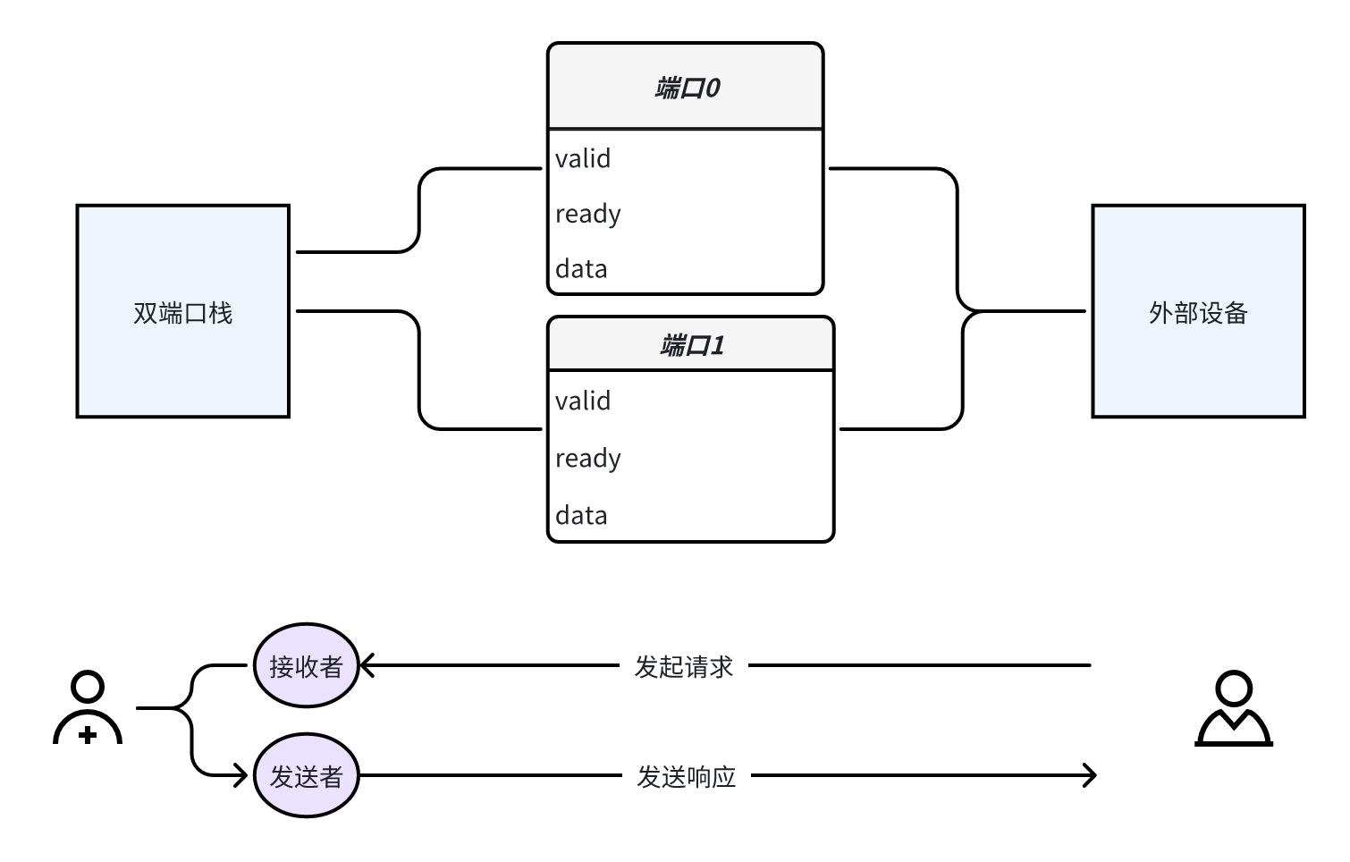
Handshake in Dual-Port Stack
You might find it strange that the dual-port stack clearly only has one module, so where do the sender and receiver come from? In fact, you can abstract out an external device. When interacting with the stack via the request port, it acts as the sender; when interacting with the stack via the response port, it acts as the receiver.
Why Specifically Discuss the Handshake Protocol
The use of the handshake protocol is incredibly common. For instance, in the design of the XiangShan processor, data interactions between most different modules adopt various handshake protocols. This is something that verification engineers frequently need to interact with. The valid-ready handshake protocol in this example is the simplest and most widely used one, which helps build a good first impression of the handshake protocol.
Dual-Port Stack Operations
Once you understand the handshake protocol and compare the request and input ports of the dual-port stack, you can roughly understand how to operate the dual-port stack.
When we want to perform an operation on the stack via a port, we first need to write the desired data and command into the input port, and then wait for the output port to return out the result.
Our definition: One stack operation = Initiate operation request + Receive response
Specifically, if we want to perform a PUSH operation on the stack:
- Initiate request:
- First, we should write the data that needs to be PUSHed into
in_data, then setin_cmdto 0 indicating a PUSH operation, and setin_validto 1 indicating the input request is valid. - Next, we need to wait for
in_readyto become 1, indicating the stack is prepared to receive an external request. At this moment, satisfying the principle of the handshake protocol:valid && ready, the PUSH request is correctly sent.
- First, we should write the data that needs to be PUSHed into
- Receive response:
- After the command is sent successfully, we need to wait for the stack’s response info at the response port. When
out_validis 1, it indicates the stack has completed the corresponding operation, and valid response info is output. At this moment, we can read the stack’s returned data fromout_data(if it was a POP operation, the return data would be placed here, but for a PUSH operation, this data is obviously invalid), and read the stack’s returned command fromout_cmd. - Then,
out_readyneeds to be set to 1 to notify the stack: the external device is now ready to receive the response information. At this moment, satisfying the principle of the handshake protocol:valid && ready, the response result is correctly sent.
- After the command is sent successfully, we need to wait for the stack’s response info at the response port. When
⚠️ Note:
If requests from both ports are valid simultaneously, the stack will prioritize processing the request from port 0.
After successfully sending a request, the currently sent data must be invalidated (by setting
in_valid); after successfully receiving a response, the external device cannot immediately be prepared to continue receiving a new signal, so we must pullout_readylow.
Building the Driven EnvironmentBefore testing the dual-port stack, we first need to use the Picker tool to build the RTL code into a Python Module. After the build is complete, we will drive the RTL code for testing through a Python script.
First, create a file named dual_port_stack.v and copy the RTL code above into this file, then execute the following command in the same folder:
picker export --autobuild=true dual_port_stack.v -w dual_port_stack.fst --sname dual_port_stack --tdir picker_out_dual_port_stack/ --lang python -e --sim verilator
💡 Note: You can refer to the picker command parameters section in the picker tutorial for the meaning of each option.
The generated driver environment is located in the dual_port_stack folder, which is the generated Python Module.
If no errors occur during automatic compilation and execution, the environment has been correctly built.
Callback-Based Driving
Challenges in Driving the Dual-Port Stack
The two ports of the dual-port stack are two independent execution logics. In the driver, these two ports may be in completely different states—for example, while port 0 is waiting for the DUT to return data, port 1 may be sending a new request. In this situation, it would be very difficult to drive the DUT using simple serial execution logic.
🔍 Think about it—how would you implement the driver? Isn’t it quite difficult?
We need a way to drive the dual-port stack in parallel. Using callback functions is one approach, and using coroutines is another. In this section, we will mainly focus on callback functions to introduce how to drive the dual-port stack.
Review of Callback Functions
A callback function is a common programming technique that allows us to pass in a function and wait for it to be called when some condition is met.
Callbacks and Parallelism: Moving the context to chip verification using picker, this condition is tied to the clock. The common approach is to call the callback function on each rising clock edge. In this way, if we have multiple ports that need to be driven, when the rising clock edge arrives, the registered ports will all call their respective callback functions, thereby achieving parallelism.
Callback Functions and State Machines: What actually drives our port execution is only one callback function. This means this function has a lot to do internally—it is responsible for the entire flow of port execution, which inevitably involves various state transitions. Therefore, writing callback functions using state machine logic is the recommended approach, as it can provide complete control over the port.
Regarding the basic usage of how to register and use callback functions, it has already been described in the section “Getting Started Part 2 — Picker Installation and Usage / Picker’s Basic Functions / Operating the DUT / Clock Operations / Registering Callback Functions.” Below, we will use the dual-port stack using callback functions as a case study to let you apply this in practice.
Introduction to the Verification Code
The verification code implementing callback functions consists of the following parts. The complete verification code is attached at the end of this subsection:
StackModel: The reference model, which simulates the actual data structure and operation behavior of the stack, responsible for comparing execution results with the DUT.SinglePortDriver: The driver for one port, responsible for sendingPUSH / POPrequests to the DUT, receiving responses, and comparing with the reference model.Defines how to drive the DUT: the
pushfunction andpopfunction assign values to the DUT for driving, implementing stack operations.Defines the dual-port stack operation state machine: implemented using callback functions, simulating the complete flow of dual-port stack operations. This is a detailed part described later.
Compares with the reference model: calls the reference model driver function in the callback function and compares with the DUT output.
test_stack(): The top-level test function, which creates drivers for the stack’sport0andport1respectively, and registers the callback functions corresponding to the two ports to achieve parallel driving.mainentry point: initializes the DUT, starts the top-level test, and finally destroys the DUT.
Among them, implementing SinglePortDriver using callback functions is the core of this lecture.
Introduction to SinglePortDriver Driving Logic
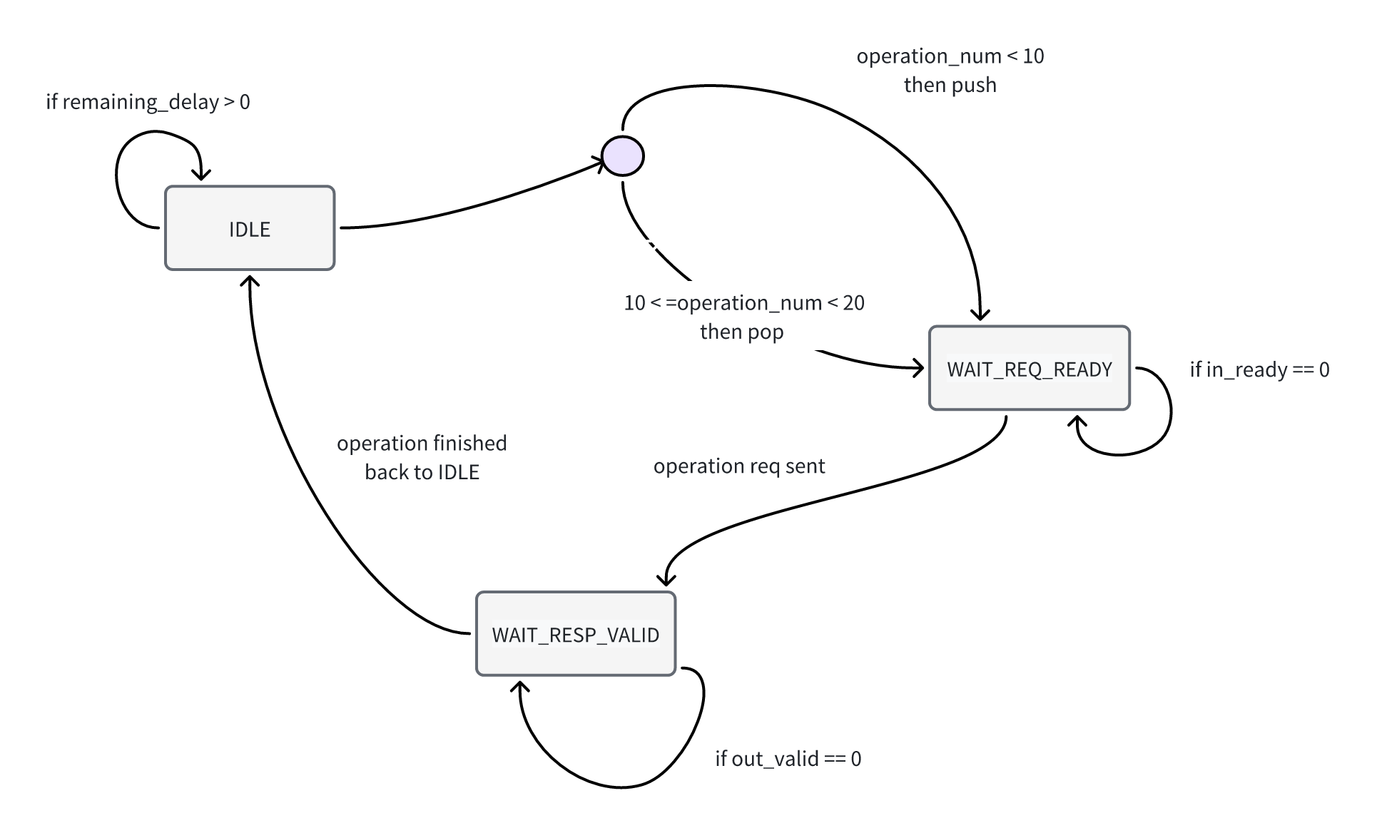
Using callback functions, we implement the dual-port stack’s driving logic as a state machine. Since the driving is implemented through callback functions, we will use several stack states as branch logic judgments within the callback function to implement the state machine. Below is a detailed introduction to the operations performed by the stack in these three states:
IDLE: Idle state, waiting for the next operationIn the idle state, you need to check the other state variable
remaining_delayto determine whether the current delay has ended. If the delay has ended, you can proceed to the next operation immediately; otherwise, continue waiting.When you need to execute the next operation, you need to check the state
operation_num(the number of operations already executed) to decide whether the next operation should bePUSHorPOP. Then call the relevant function to assign a value to the port once and switch the state toWAIT_REQ_READY.
Code Reference:
if self.status == self.Status.IDLE: # IDLE: idle state, waiting for delay to end before executing next operation if self.remaining_delay == 0: if self.operation_num < 10: # First ten operations are PUSH operations self.push() elif self.operation_num < 20: # Last ten operations are POP operations, during which comparison between reference model and DUT output is performed self.pop() else: return self.operation_num += 1 # After completing a PUSH or POP operation, increment the operation count by 1 self.status = self.Status.WAIT_REQ_READY # Switch state to WAIT_REQ_READY else: self.remaining_delay -= 1 # Each time the callback function is called, when the state machine is in IDLE state and delay is not 0, decrement delay by 1 # This is equivalent to waiting time -1 for each clock cycle advancedWAIT_REQ_READY: Waiting for the stack to be ready to receive requestsAfter an external request is sent (
in_validis asserted), you need to wait for thein_readysignal to be asserted to ensure the stack is ready to receive the request signal.After the request is accepted correctly, you need to set
in_validto 0 and setout_readyto 1 at the same time, indicating that the sent data is now invalid and the external device is ready to receive the response signal.
Code Reference:
if self.status == self.Status.WAIT_REQ_READY: # WAIT_REQ_READY: waiting for the stack to be ready to receive signals if self.port_dict["in_ready"].value == 1: # After the stack is ready to receive signals, the signal is successfully sent self.port_dict["in_valid"].value = 0 # Set the currently sent data to invalid self.port_dict["out_ready"].value = 1 # Manually control the external device to be ready to receive the response self.status = self.Status.WAIT_RESP_VALID # After completing the request sending, switch state to WAIT_RESP_VALID if self.port_dict["in_cmd"].value == self.BusCMD.PUSH.value: # Synchronize the operation on the reference model self.model.commit_push(self.port_dict["in_data"].value)WAIT_RESP_VALID: Waiting for the stack to be ready with the response signal- After the request is accepted correctly, you need to wait for the DUT’s reply, i.e., wait for the
out_validsignal to be asserted. - When the
out_validsignal is asserted, the valid response signal has been output, so setout_readyto 0, indicating that the external device is not yet ready to receive a new response signal because it just received the response signal. - Finally, switch the state to
IDLE, indicating that the operation is complete and waiting for the next operation.
Code Reference:
elif self.status == self.Status.WAIT_RESP_VALID: # WAIT_RESP_VALID: waiting for the response data to be valid if self.port_dict["out_valid"].value == 1: # Response data is valid, the external device can successfully read the data self.port_dict["out_ready"].value = 0 # The external device just finished reading the response data and is not ready to receive new signals self.status = self.Status.IDLE # After completing the operation, switch state to IDLE self.remaining_delay = random.randint(0, 5) # Generate a random delay after completing a stack operation if self.port_dict["out_cmd"].value == self.BusCMD.POP_OKAY.value: # If it is a POP operation, we compare the reference model and the DUT's read data self.model.commit_pop(self.port_dict["out_data"].value)- After the request is accepted correctly, you need to wait for the DUT’s reply, i.e., wait for the
State Machine Transition Diagram
| Current State | Transition Condition | Next State | Behavior Description |
|---|---|---|---|
| IDLE | remaining_delay == 0 | WAIT_REQ_READY | Initiate PUSH or POP request |
| WAIT_REQ_READY | in_ready == 1 | WAIT_RESP_VALID | DUT accepts request, waiting for response |
| WAIT_RESP_VALID | out_valid == 1 | IDLE | Response is valid, operation complete, return to idle and wait for next request |
Introduction to the Reference Model Code
Defining the reference model is for comparing with the behavior of the actual hardware module. While ensuring the correctness of the reference model, we perform the same operations on both the reference model and the DUT. When the behavior of the reference model is inconsistent with the DUT’s behavior, it means a bug exists in the DUT.
Below is our example of a dual-port stack reference model, which uses assertions to compare the behavior results of the reference model with the DUT’s behavior results:
class StackModel:
    def __init__(self):
        self.stack = []    # Use a list to simulate the internal storage of the stack

    def commit_push(self, data):    # data is the data being pushed into the stack, consistent with the data pushed into the DUT
        self.stack.append(data)
        print("push", data)

    def commit_pop(self, dut_data):    # dut_data is the data being popped from the DUT
        print("Pop", dut_data)         # Input this parameter to compare with the data popped from the reference model
        model_data = self.stack.pop()
        assert model_data == dut_data, f"The model data {model_data} is not equal to the dut data {dut_data}"    # Use assertions for comparison
        print(f"Pass: {model_data} == {dut_data}")
Simulating stack data structure: using a list
self.stackto simulate the stack’s internal storage.Simulating stack operations:
push: define the function
commit_push, call the list’sappendfunction to simulate the stack push operation.pop: define the function
commit_pop, call the list’spopfunction to simulate the stack pop operation.
Comparing DUT results:
- Use assertions to compare the result output by the reference model with the result output by the DUT when executing the pop operation.
Complete Verification Code
import random
from dual_port_stack import *
from enum import Enum

class StackModel:
    def __init__(self):
        self.stack = []    # Use a list to simulate the internal storage of the stack

    def commit_push(self, data):    # data is the data being pushed into the stack, consistent with the data pushed into the DUT
        self.stack.append(data)
        print("push", data)

    def commit_pop(self, dut_data):    # dut_data is the data being popped from the DUT
        print("Pop", dut_data)         # Input this parameter to compare with the data popped from the reference model
        model_data = self.stack.pop()
        assert model_data == dut_data, f"The model data {model_data} is not equal to the dut data {dut_data}"    # Use assertions for comparison
        print(f"Pass: {model_data} == {dut_data}")

class SinglePortDriver:
    class Status(Enum):    # Define the three states of the state machine; callback functions typically drive the DUT using state machine logic
        IDLE = 0
        WAIT_REQ_READY = 1
        WAIT_RESP_VALID = 2
    class BusCMD(Enum):    # Bus control signals
        PUSH = 0           # Stack request control signal value
        POP = 1
        PUSH_OKAY = 2      # Stack response control signal value
        POP_OKAY = 3

    def __init__(self, dut, model: StackModel, port_dict):
        self.dut = dut    # Initialize the dut member variable in the driver function
        self.model = model    # Initialize the reference model member variable in the driver function
        self.port_dict = port_dict    # port_dict stores key-value pairs of port names and DUT port values, allowing DUT assignment through it

        self.status = self.Status.IDLE # Initial state is IDLE
        self.operation_num = 0  # Current cumulative completed operation count
        self.remaining_delay = 0 # Delay time: after an operation completes, a random delay is generated; execute the next operation after the delay reaches 0

    def push(self):    # Drive a PUSH operation on the DUT
        self.port_dict["in_valid"].value = 1
        self.port_dict["in_cmd"].value = self.BusCMD.PUSH.value
        self.port_dict["in_data"].value = random.randint(0, 2**32-1)

    def pop(self):    # Drive a POP operation on the DUT
        self.port_dict["in_valid"].value = 1
        self.port_dict["in_cmd"].value = self.BusCMD.POP.value

    def step_callback(self, cycle):    # Callback function, drives the DUT in state machine mode
        if self.status == self.Status.WAIT_REQ_READY:    # WAIT_REQ_READY: waiting for the stack to be ready to receive signals
            if self.port_dict["in_ready"].value == 1:    # After the stack is ready to receive signals, the signal is successfully sent
                self.port_dict["in_valid"].value = 0    # Set the currently sent data to invalid
                self.port_dict["out_ready"].value = 1    # Manually control the external device to be ready to receive the response
                self.status = self.Status.WAIT_RESP_VALID    # After completing the request sending, switch state to WAIT_RESP_VALID

                if self.port_dict["in_cmd"].value == self.BusCMD.PUSH.value:    # Synchronize the operation on the reference model
                    self.model.commit_push(self.port_dict["in_data"].value)

        elif self.status == self.Status.WAIT_RESP_VALID:    # WAIT_RESP_VALID: waiting for the response data to be valid
            if self.port_dict["out_valid"].value == 1:      # Response data is valid, the external device can successfully read the data
                self.port_dict["out_ready"].value = 0      # The external device just finished reading the response data and is not ready to receive new signals
                self.status = self.Status.IDLE              # After completing the operation, switch state to IDLE
                self.remaining_delay = random.randint(0, 5)   # Generate a random delay after completing a stack operation

                if self.port_dict["out_cmd"].value == self.BusCMD.POP_OKAY.value: # If it is a POP operation, we compare the reference model and the DUT's read data
                    self.model.commit_pop(self.port_dict["out_data"].value)

        if self.status == self.Status.IDLE:    # IDLE: idle state, waiting for delay to end before executing next operation
            if self.remaining_delay == 0:
                if self.operation_num < 10:    # First ten operations are PUSH operations
                    self.push()
                elif self.operation_num < 20: # Last ten operations are POP operations, during which comparison between reference model and DUT output is performed
                    self.pop()
                else:
                    return

                self.operation_num += 1    # After completing a PUSH or POP operation, increment the operation count by 1
                self.status = self.Status.WAIT_REQ_READY   # Switch state to WAIT_REQ_READY
            else:
                self.remaining_delay -= 1    # Each time the callback function is called, when the state machine is in IDLE state and delay is not 0, decrement delay by 1
                                             # This is equivalent to waiting time -1 for each clock cycle advanced
def test_stack(stack):    # Parameter is the dual-port stack DUT instance
```model = StackModel()    # Instantiate the reference model

    port0 = SinglePortDriver(stack, model, {    # Instantiate the port 0 interface driver
        "in_ready": stack.in0_ready,            # Dictionary storing port name and DUT port value key-value pairs, can be used to assign values to DUT
        "in_valid": stack.in0_valid,
        "in_data": stack.in0_data,
        "in_cmd": stack.in0_cmd,
        "out_valid": stack.out0_valid,
        "out_ready": stack.out0_ready,
        "out_data": stack.out0_data,
        "out_cmd": stack.out0_cmd,
    })

    port1 = SinglePortDriver(stack, model, {    # Instantiate port 1's driver
        "in_valid": stack.in1_valid,
        "in_ready": stack.in1_ready,
        "in_data": stack.in1_data,
        "in_cmd": stack.in1_cmd,
        "out_valid": stack.out1_valid,
        "out_ready": stack.out1_ready,
        "out_data": stack.out1_data,
        "out_cmd": stack.out1_cmd,
    })

    dut.StepRis(port0.step_callback)    # Register callback function in DUT, called on clock rising edge for port 0 driver
    dut.StepRis(port1.step_callback)    # Register callback function in DUT, called on clock rising edge for port 1 driver

    dut.Step(200)    # Advance clock by 200 cycles, during which the two drivers' callback functions execute concurrently


if __name__ == "__main__":
    dut = DUTdual_port_stack()    # Create dut
    dut.InitClock("clk")          # Initialize clock signal
    test_stack(dut)               # Start test
    dut.Finish()                  # Destroy dut
Running the Test
Create an example.py file in picker_out_dual_port_stack, copy the above code into it, and then execute the following command:
cd picker_out_dual_port_stack
python3 example.py
You can run the test code for this example directly, and you will see output similar to the following:
...
push 77
push 140
push 249
push 68
push 104
push 222...
Pop 43
Pass: 43 == 43
Pop 211
Pass: 211 == 211
Pop 16
Pass: 16 == 16
Pop 255
Pass: 255 == 255
Pop 222
Pass: 222 == 222
Pop 104
...
Advantages and Disadvantages of Callback-Driven Approach
By using callback functions, we can complete parallel driving of the DUT. As shown in this example, we implemented driving of two ports with independent execution logic through two callback functions. Callback functions provide a simple method for parallel driving in simple scenarios.
However, this example also clearly exposes the limitations of the callback function approach: implementing even a simple “request-response” flow requires developers to manually maintain complex state machine logic. As the interaction logic increases, this approach quickly becomes difficult to manage and scale, increasing the cost of developing and debugging verification code. This becomes an efficiency bottleneck in projects that require rapid iteration and verification of complex designs (including many challenging open-source projects or future crowdsourcing verification tasks).
Coroutine-Based Driving
Although callback functions provide a way to achieve parallel operations, they split the complete execution flow into multiple function calls and require maintaining a large amount of intermediate state, making code writing and debugging relatively complex.
In this example, we will introduce a coroutine-based driving method that can not only achieve parallel operations but also avoid the problems brought by callback functions.
Review of Coroutines
A coroutine is a “lightweight” thread. Through coroutines, you can achieve concurrent execution behavior similar to threads, but with much lower overhead. The implementation principle is that the coroutine library implements an EventLoop running on a single thread, and programmers can define several coroutines and add them to the EventLoop, which is responsible for scheduling these coroutines.
Generally speaking, the coroutines we define continue executing during execution until encountering a “event” that needs to be waited for. At this point, the EventLoop pauses the execution of that coroutine and schedules other coroutines to run. When the event occurs, the EventLoop wakes up the coroutine again and continues execution.
We provided a detailed explanation of related concepts in the section Beginner Tutorial Part 3 / Using the Asynchronous Environment. If you encounter problems, you can review that section to clarify related concepts.
Review of Asynchronous Waiting in Picker
For parallel execution in hardware verification, the concurrency characteristic of coroutines is exactly what we need. We can create multiple coroutines to complete multiple driving tasks in verification.
Waiting for Clock Advancement
We can wait for a clock: This is equivalent to treating clock advancement as an IO event, waiting for this event in a coroutine. When the clock signal arrives, the EventLoop wakes up all coroutines waiting for the clock, making them continue execution until they wait for the next clock signal.
- Picker allows coroutines to use the
await AStepfunction for this kind of waiting:
- Picker allows coroutines to use the
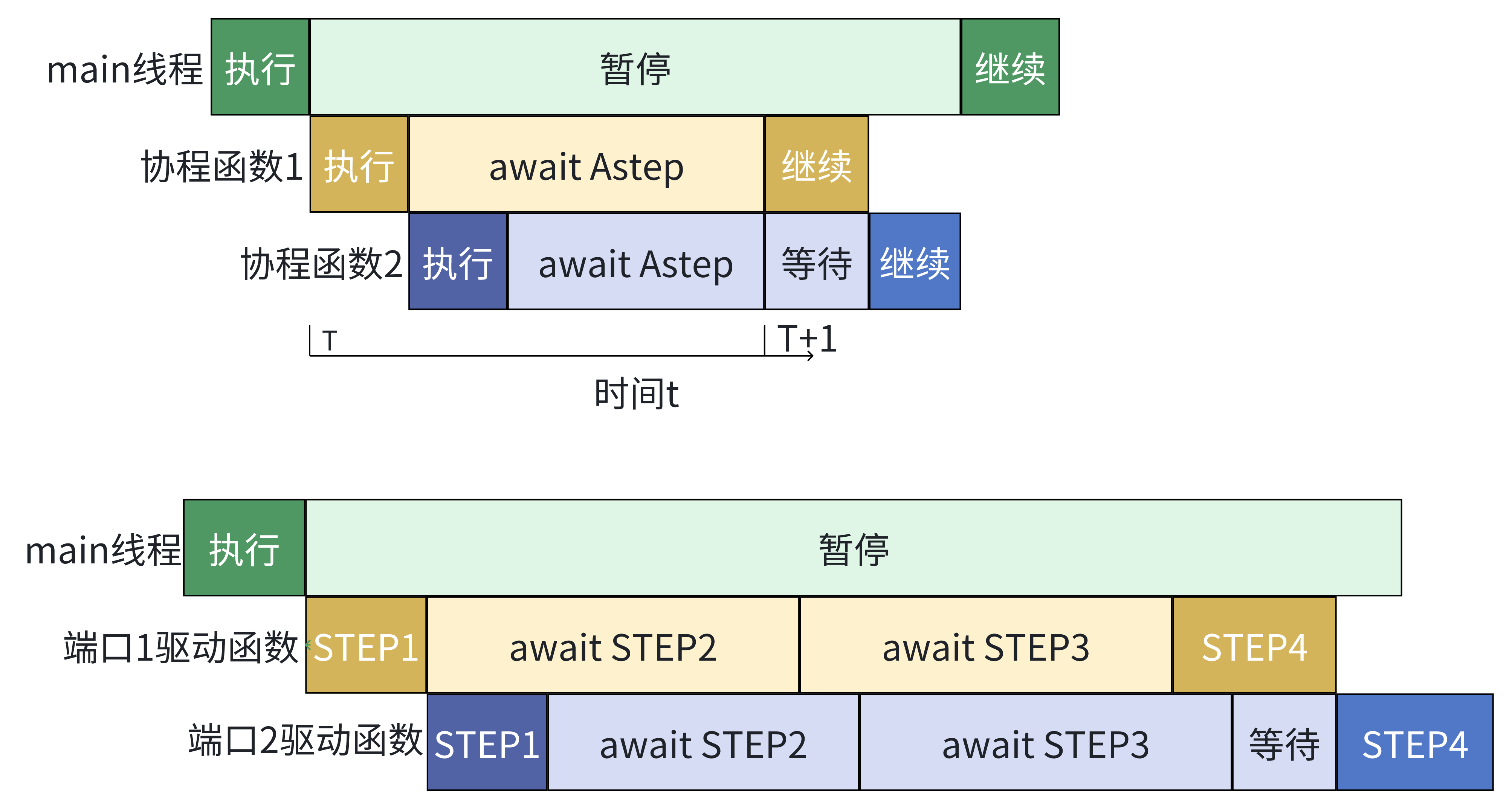
From a macro perspective, coroutine 1 and coroutine 2 are concurrently executed, but this is actually achieved through coroutine switching
Waiting for Condition to Be Met
We can wait for a condition: This is equivalent to treating the condition being met as an event, waiting for the condition to be met in a coroutine. Until the condition is met, the EventLoop wakes up the coroutine waiting for that condition and continues execution.
- Picker allows coroutines to use the
await AConditionfunction for this kind of waiting.
- Picker allows coroutines to use the
Introduction to SinglePortDriver Driving Logic
We already know that we can easily drive the DUT in parallel using coroutines. For a dual-port stack, the objects of parallel driving are obviously the two ports of the stack. For each port, we only need to treat it as an independent execution flow and drive it. Since this is the case, the driving process is consistent with what was introduced in the section Dual-Port Stack Introduction / Dual-Port Stack Operations. The only thing to note is that our conditional waiting in the operations is implemented through waiting for asynchronous functions in Picker (await AStep, await ACondition, etc.).
The process of driving response operations is also similar. We assign values through the interface to let the external device prepare to receive the stack response signal. After completing the assignment, we wait for the condition that the response signal is valid to be met. Once the condition is met, we lower the “external device ready to receive response” signal, and when the operation is POP, we perform the POP operation on the reference model.
In the SinglePortDriver class, we encapsulate one operation into the exec_once function. In the main function, we only need to first call exec_once(is_push=True) 10 times to complete the PUSH operation, then call exec_once(is_push=False) 10 times to complete the POP operation.
In the exec_once function, we first call the send_req function to send a request, then call the receive_resp function to receive the response, and finally wait for a random number of clock cycles to simulate delay. During the waiting process, we call await AStep to achieve concurrency.
Complete Verification Code
import asyncio
import random
from dual_port_stack import *
from enum import Enum

class StackModel:    # Reference model remains unchanged
    def __init__(self):
        self.stack = []

    def commit_push(self, data):
        self.stack.append(data)
        print("Push", data)

    def commit_pop(self, dut_data):
        print("Pop", dut_data)
        model_data = self.stack.pop()
        assert model_data == dut_data, f"The model data {model_data} is not equal to the dut data {dut_data}"
        print(f"Pass: {model_data} == {dut_data}")

class SinglePortDriver:
    class BusCMD(Enum):
        PUSH = 0
        POP = 1
        PUSH_OKAY = 2
        POP_OKAY = 3

    def __init__(self, dut, model: StackModel, port_dict):
        self.dut = dut
        self.model = model
        self.port_dict = port_dict

    async def send_req(self, is_push):    # Request initiating driver function, determines push or pop operation via is_push signal
        self.port_dict["in_valid"].value = 1    # Set assignment operations required for operation request
        self.port_dict["in_cmd"].value = self.BusCMD.PUSH.value if is_push else self.BusCMD.POP.value
        self.port_dict["in_data"].value = random.randint(0, 2**8-1)
        await self.dut.AStep(1)

        await self.dut.ACondition(lambda: self.port_dict["in_ready"].value == 1)    # Wait for stack to be ready to receive request, achieving parallelism
        self.port_dict["in_valid"].value = 0    # Complete sending request, set data to invalid

        if is_push:    # When operation is push, need to drive reference model to complete push
            self.model.commit_push(self.port_dict["in_data"].value)

    async def receive_resp(self):    # Response receiving driver function
        self.port_dict["out_ready"].value = 1    # Set external device ready signal to receive response
        await self.dut.AStep(1)

        await self.dut.ACondition(lambda: self.port_dict["out_valid"].value == 1)    # Wait for response information to be valid, achieving parallelism
        self.port_dict["out_ready"].value = 0

        if self.port_dict["out_cmd"].value == self.BusCMD.POP_OKAY.value:    # When operation is POP and executed successfully, compare with reference model
            self.model.commit_pop(self.port_dict["out_data"].value)

    async def exec_once(self, is_push):    # Define driver port to perform one execution
        await self.send_req(is_push)       # Note!! Here the request and response are serial, not parallel,
        await self.receive_resp()          # because they are not registered to an event loop!!
        for _ in range(random.randint(0, 5)):    # Random delay after completing one operation (request + response)
            await self.dut.AStep(1)

    async def main(self):    # Driver class main function, execute 10 push request operations, then execute 10 pop request operations
        for _ in range(10):
            await self.exec_once(is_push=True)
        for _ in range(10):
            await self.exec_once(is_push=False)

async def test_stack(stack):
    model = StackModel()

    port0 = SinglePortDriver(stack, model, {
        "in_valid": stack.in0_valid,
        "in_ready": stack.in0_ready,
        "in_data": stack.in0_data,
        "in_cmd": stack.in0_cmd,
        "out_valid": stack.out0_valid,
        "out_ready": stack.out0_ready,
        "out_data": stack.out0_data,
        "out_cmd": stack.out0_cmd,
    })

    port1 = SinglePortDriver(stack, model, {
        "in_valid": stack.in1_valid,
        "in_ready": stack.in1_ready,
        "in_data": stack.in1_data,
        "in_cmd": stack.in1_cmd,
        "out_valid": stack.out1_valid,
        "out_ready": stack.out1_ready,
        "out_data": stack.out1_data,
        "out_cmd": stack.out1_cmd,
    })

    asyncio.create_task(port0.main())    # Add port 0 driver's main coroutine to event loop
    asyncio.create_task(port1.main())    # The main coroutines of the two port drivers will be concurrently executed by the event loop
    await asyncio.create_task(dut.RunStep(200))    # Advance clock by 200 clock cycles

if __name__ == "__main__":
    dut = DUTdual_port_stack()
    dut.InitClock("clk")
    asyncio.run(test_stack(dut))    # Start event loop
    dut.Finish()
Running the Test
Create example.py in the picker_out_dual_port_stack folder, copy the above code into it, and then execute the following command:
cd picker_out_dual_port_stack
python3 example.py
You can run the test code for this example directly, and you will see output similar to the following:
...
Push 141
Push 102
Push 63
Push 172
Push 208
Push 130
Push 151
...
Pop 102
Pass: 102 == 102
Pop 138
Pass: 138 == 138
Pop 56
Pass: 56 == 56
Pop 153
Pass: 153 == 153
Pop 129
Pass: 129 == 129
Pop 235P
ass: 235 == 235
Pop 151
...
In the output, you can see the data for each PUSH and POP operation, as well as the result of each POP operation. If there are no error messages in the output, the test passes.
Advantages and Disadvantages of Coroutine-Driven Approach
Through coroutine functions, we can well achieve parallel operations while avoiding the problems brought by callback functions. Each independent execution flow can be completely preserved and implemented as a coroutine, greatly facilitating code writing.
However, in more complex scenarios, you will find that having many coroutines makes synchronization and timing management between coroutines complex. This phenomenon is particularly evident when you need to synchronize between two coroutines that do not directly interact with the DUT.
In this situation, you need a set of standard coroutine writing specifications and proven design patterns to help you build higher-quality verification code. The Toffee library we introduced in the previous lecture was developed precisely to meet these needs. It provides a complete set of coroutine-based verification code design patterns that can help you better organize and manage complex verification environments. By using Toffee, you can write verification code more standardized and efficiently. If you are interested, you can learn more from here.