Lecture 2 · Installation and Usage of Picker
Introduces the installation and use of Picker with Python as an example
Overview
This lecture introduces Picker, a chip verification auxiliary tool that can package RTL design modules into dynamic libraries and provide multi-language programming interfaces.
Starting from this course, we will use Python as the high-level language for chip verification, and related examples will also be written in Python.
The main contents of this course include:
Introduction and advantages of the Picker tool
Installation and configuration process (Verilator, Swig, Verible, etc.)
Explanation of basic functions (DUT creation, port operation, clock control)
Detailed explanation of Picker command parameters
Synchronous FIFO practical exercise
Through learning, you will master how to use Picker and Python for efficient chip verification to improve verification efficiency.
Introduction to Picker
Picker is an auxiliary tool for chip verification with two main functions:
Packaging RTL design verification modules: Picker can package RTL design verification modules (
.v/.scala/.sv) into dynamic libraries, and provide programming interfaces in various high-level languages (currently supporting C++, Python, Java, Scala, Golang) to drive circuits.Encapsulating UVM-TLM transactions into other languages: Picker can perform automated TLM code encapsulation based on user-provided UVM sequence_items to provide communication interfaces between UVM and other high-level languages (e.g., Python). This tool allows users to perform unit testing of chips based on existing software testing frameworks, such as pytest, junit, TestNG, go test, etc.
Advantages of verification based on Picker:
Does not leak RTL designs: After Picker conversion, original design files (
.v) are transformed into binary files (.so). After separation from original design files, verification can still be performed, and verifiers cannot obtain the RTL source code.Reduces compilation time: When the DUT (Design Under Test) is stable, it only needs to be compiled once (packaged into an
.sofile).Broad user base: It offers many programming interfaces to cover developers across different languages.
Rich software ecosystem: Supports ecosystems such as Python3, Java, and Golang.
Automated UVM transaction encapsulation: Realizes communication between UVM and Python by automatically encapsulating UVM transactions.
RTL simulators currently supported by Picker:
Verilator
Synopsys VCS
Installation of Picker
Before using Picker for chip verification, we must first complete the installation of Picker and its dependency tools. This section will introduce installation steps and potential issues you might encounter.
Docker Images
We provide pre-packaged Docker images:
Containing Picker:
ghcr.io/xs-mlvp/envbase:latestContaining Picker and Toffee:
ghcr.io/xs-mlvp/envfull:latest
For specific usage refer to: https://github.com/XS-MLVP/tutorial-records
System Requirements
Picker needs to be run in a Linux system environment, we recommend using the following distributions:
Debian 12/13
Ubuntu 22.04/24.04
Note: The following commands are only guaranteed to work in the Linux distributions listed above. If you use other distributions, please resolve any issues on your own.
Dependency Installation
Picker depends on the following tools:
Basic compilation tools (e.g., gcc, cmake, etc.)
lcov
Verilator
Swig
Verible
Next, we will complete the installation of these dependency tools step by step.
Install Basic Compilation Tools
sudo apt install -y build-essential git cmake python3-venv libpython3-dev time lcov
Install Verilator
Check Available Versions
First, check the Verilator version provided by the package management tool:
apt show verilator
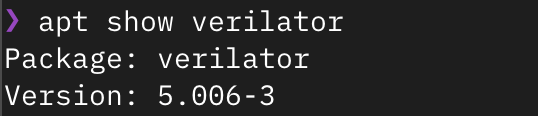
As shown in the figure above, if the version number (Version) is ≥ 4.218, you can install it directly via the package manager:
sudo apt install -y verilator
Otherwise, you need to compile and install Verilator. It is recommended to install the latest version.
Note: Starting from Verilator 5.030, the merge strategy for code coverage statistics has changed, but it does not affect functional verification.
Compile and Install Verilator
Get the source code:
# Clone the code from github
git clone https://github.com/verilator/verilator.git
# WARNING!!! If the clone fails, you can consider using the following command to clone from gitee
git clone https://gitee.com/mirrors/Verilator verilator

# Enter the repository
cd verilator
Then switch the branch to the stable version, install the tools required for compilation, and then compile and install:
# Switch branch
git checkout stable
# Install dependencies
sudo apt install -y help2man perl perl-doc flex bison autoconf

# Compile
autoconf
./configure
make -j
# Install
sudo -E make install
Then enter verilator -version in the command line. If similar content appears as shown below, the installation is successful:

Check Available Versions
First, check the Swig version provided by the package management tool:
apt show swig
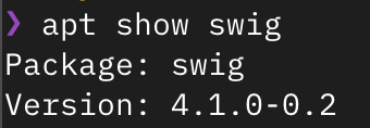
As shown in the figure above, if the version number (Version) is ≥ 4.2.0, you can install it directly via the package manager:
sudo apt install -y swig
Otherwise, you need to compile and install swig. It is recommended to install the latest version.
Compile and Install Swig
If you previously installed Swig via the package manager, please remove it first:
sudo apt purge -y swig
First, open the Swig source code download website https://www.swig.org/download.html
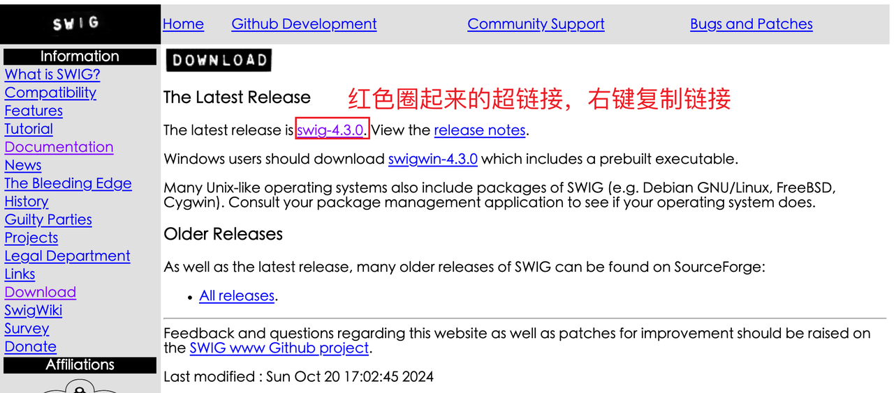
At the time of writing this tutorial, the link to the source code we got is wget http://prdownloads.sourceforge.net/swig/swig-4.3.1.tar.gz
❓ What should I do if the Swig website version I open is different from the screenshot? No problem, as long as it is not lower than 4.2.0.
Next, we will complete the installation of these dependency tools step by step.
Install Basic Compilation Tools
sudo apt install -y build-essential git cmake python3-venv libpython3-dev time lcov
Install Verilator
Check Available Versions
First, check the Verilator version provided by the package management tool:
apt show verilator
As shown in the figure above, if the version number (Version) is ≥ 4.218, you can install it directly via the package manager:
sudo apt install -y verilator
Otherwise, you need to compile and install Verilator. It is recommended to install the latest version.
Note: Starting from Verilator 5.030, the merge strategy for code coverage statistics has changed, but it does not affect functional verification.
Compile and Install Verilator
Get the source code:
# Clone the code from github
git clone https://github.com/verilator/verilator.git
# WARNING!!! If the clone fails, you can consider using the following command to clone from gitee
git clone https://gitee.com/mirrors/Verilator verilator

# Enter the repository
cd verilator
Then switch the branch to the stable version, install the tools required for compilation, and then compile and install:
# Switch branch
git checkout stable
# Install dependencies
sudo apt install -y help2man perl perl-doc flex bison autoconf

# Compile
autoconf
./configure
make -j
# Install
sudo -E make install
Then enter verilator -version in the command line. If similar content appears as shown below, the installation is successful:
Check Available Versions
First, check the Swig version provided by the package management tool:
apt show swig
As shown in the figure above, if the version number (Version) is ≥ 4.2.0, you can install it directly via the package manager:
sudo apt install -y swig
Otherwise, you need to compile and install swig. It is recommended to install the latest version.
Compile and Install Swig
If you previously installed Swig via the package manager, please remove it first:
sudo apt purge -y swig
First, open the Swig source code download website https://www.swig.org/download.html
At the time of writing this tutorial, the link to the source code we got is wget http://prdownloads.sourceforge.net/swig/swig-4.3.1.tar.gz
❓ What should I do if the Swig website version I open is different from the screenshot? No problem, as long as it is not lower than 4.2.0. Then download the swig source code in Linux:
# Note! The downloaded version number might be different, subject to actual download results
# Download swig source code. If you are familiar with Linux, you can use your preferred method to download it
sudo apt install -y wget # Install wget
wget http://prdownloads.sourceforge.net/swig/swig-4.3.1.tar.gz

tar xvf swig-4.3.1.tar.gz # Extract in the current directory
cd swig-4.3.1 # Enter the source code folder

sudo apt install -y python3-pip libpcre2-dev # Install dependencies
# Configure
./configure
make -j
# Install
sudo -E make install
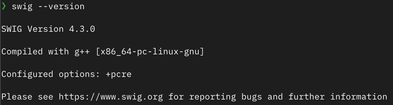
Execute the command swig --version. If output similar to the image below appears, the installation is successful:
Install Verible
Download the Verible binary from GitHub: https://github.com/chipsalliance/verible/releases
Download
Download the Verible binary program (x86) and extract it:
# Note! The downloaded version number might be different, subject to actual download results
# Download verible. If you are familiar with Linux, you can use your preferred method to download it
sudo apt install -y wget # Install wget
wget https://github.com/chipsalliance/verible/releases/download/v0.0-3958-g7aae5c08/verible-v0.0-3958-g7aae5c08-linux-static-x86_64.tar.gz

# Extract
tar xvf verible-v0.0-3958-g7aae5c08-linux-static-x86_64.tar.gz
⚠️ Warning: You need to place the extracted folder in a safe directory properly. Do not move it after the environment variables have been configured.
Configure Environment Variables
Execute in the terminal:
echo $SHELL
If the output contains bash, it means you are using Bash Shell. The following configuration is based on Bash; please adjust for other Shells by yourself.
Then go to the folder where verible was extracted. Using the tutorial as an example, after entering the ls command, you can see the verible-v0.0-3958-g7aae5c08-linux-static-x86_64 folder:
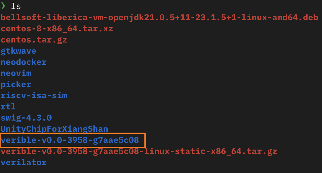
Next, add the environment variables:
# verible-v0.0-3958-g7aae5c08 is subject to the actual download result, then replace it with your extracted folder
echo "export PATH=\$PATH:$(realpath verible-v0.0-3958-g7aae5c08)/bin" >> ~/.bashrc
source ~/.bashrc
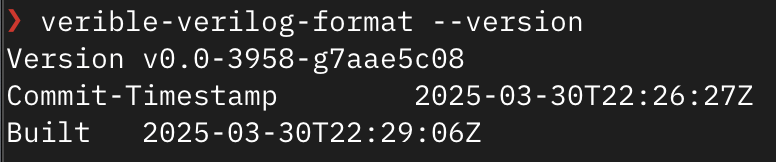
Execute verible-verilog-format --version. If output similar to the below image appears, it means the installation was successful:
Picker Installation
After completing the installation of all dependency tools, you can now install Picker itself.
First, download the source code of Picker and enter the repository:
git clone https://github.com/XS-MLVP/picker.git --depth=1
cd picker
Then build and install:
make # Compile
sudo -E make install # Install
⚠️ Note: Support for other languages can be enabled using
make BUILD_XSPCOMM_SWIG=python,java,scala,golang,lua -j. The development environment for each language must be configured by yourself.
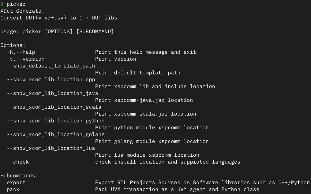
After installation, executing the picker command will yield the following output:
After completing the installation, run the following examples to verify if the installation is correct:
bash example/Adder/release-verilator.sh --lang python
bash example/RandomGenerator/release-verilator.sh --lang python
After a successful run, you will see the testing process and results for the Adder and Random Number Generator.
Basic Features of Picker
After successfully installing Picker, we will learn how to use it for DUT (Design Under Test) creation and operational methods.
DUT Creation
Take the Random Number Generator as an example.
First, create an example folder and enter it.
Note, the subsequent operations are all within the
examplefolder.
Create a RandomGenerator.v file in the example folder with the following content:
module RandomGenerator (
    input wire clk,
    input wire reset,
    input [15:0] seed,
    output [15:0] random_number
);
    reg [15:0] lfsr;

    always @(posedge clk or posedge reset) begin
        if (reset) begin
            lfsr <= seed;
        end else begin
            lfsr <= {lfsr[14:0], lfsr[15] ^ lfsr[14]};
        end
    end

    assign random_number = lfsr;
endmodule
Create DUT Class
Use the export command of Picker to create the DUT class:
picker export RandomGenerator.v --sname RandomGenerator -w RandomGenerator.fst --lang python --sim verilator
Command parameters explained:
RandomGenerator.v: Specify the RTL design file--sname RandomGenerator: Specify the top-level module name-w RandomGenerator.fst: Enable waveform output, specify the waveform filename--lang python: Generate the DUT in Python--sim verilator: Use Verilator as the simulator
After the execution is completed, a folder of the same name will be generated, containing the DUT class DUTRandomGenerator, with the directory structure:
.
├── RandomGenerator # Generated by Picker
│   ├── example.py
│   ├── __init__.py
│   ├── libUT_RandomGenerator.py
│   ├── libUTRandomGenerator.so
│   ├── pli.tab
│   ├── signals.json
│   ├── _UT_RandomGenerator.so
│   └── xspcomm
└── RandomGenerator.v # Design file of the Random Number Generator
Instantiate DUT Class
Now the DUT class can be instantiated via Python code. Create a test_dut.py file:
from RandomGenerator import *

if __name__ == "__main__":
    dut = DUTRandomGenerator() # Create DUT
    dut.Finish()
You can successfully run this file using python3 test_dut.py.
In the above code, we first instantiated the random number generator’s DUT, and then called the dut.Finish() method.
About Finish() Method
The Finish() method is a key function in simulation control. It has the following primary functionalities:
End simulation: Normally terminate the simulation process
Save waveform file: Write the waveform data recorded during the simulation to a file in a specified format (e.g., .fst)
Generate coverage file: If coverage collection is enabled, the corresponding coverage data file will be generated4. Release resources: Clean up the memory and other system resources allocated during simulation
If you need to generate a waveform file or coverage report, be sure to call the Finish() method at the end of the simulation. Otherwise, the waveform and coverage data will not be saved.
Operating the DUT
After creating the DUT class, we need to learn how to operate it, including reading and writing ports, controlling the clock, and monitoring internal signals.
This section will use the random number generator as an example to detail all aspects of DUT operation, and will use an instance of DUTRandomGenerator to demonstrate related operations.
Assume the directory structure is as follows:
.
├── RandomGenerator
│   ├── example.py
│   ├── __init__.py
│   ├── libUT_RandomGenerator.py
│   ├── libUTRandomGenerator.so
│   ├── pli.tab
│   ├── signals.json
│   ├── _UT_RandomGenerator.so
│   └── xspcomm
│
├── example.py # Assume all code is located in this file
└── RandomGenerator.v # Design file of the random number generator
Port Operations
All ports of the DUT and its exported internal signals are defined in the DUT class as member variables. The type of these member variables is XData, which Picker uses to represent the data of circuit pins.
We can read the signal values in the following ways:
from RandomGenerator import *

if __name__ == "__main__":
    dut = DUTRandomGenerator()           # Create DUT
    rand = dut.random_number.value       # Read the value of the random_number pin, equivalent to `rand = dut.random_number.U()`
    rand_lsb = dut.random_number[0]      # Read the LSB of the random_number pin
    rand_signed = dut.random_number.S()  # Read the value of the random_number pin as a signed type
    dut.Finish()
To assign a value to a port:
from RandomGenerator import *

if __name__ == "__main__":
    dut = DUTRandomGenerator()    # Create DUT
    dut.seed.value = 12345        # Decimal assignment
    dut.seed.value = 0b11011      # Binary assignment
    dut.seed.value = 0o12345      # Octal assignment
    dut.seed.value = 0x12345      # Hexadecimal assignment
    dut.seed.value = -1           # Assign 1 to all bits
    x = 3
    dut.seed.value = x            # Equivalent to a.Set(x)
    dut.seed[1] = 0               # Assign a value to bit 1
    dut.seed.value = "x"          # Assign high impedance
    dut.seed.value = "z"          # Assign unknown state
    dut.Finish()
XData Write Modes
In Picker, XData is the representation of circuit pin data, supporting three different write modes:
Immediate Write Mode (Imme): Data is written to the target immediately, independent of the clock.
Rising Edge Write Mode (Rise): Data is written to the target only at the rising edge of the clock signal. This is the default write mode.
Falling Edge Write Mode (Fall): Data is written to the target only at the falling edge of the clock signal.
These three write modes can be switched via the SetWriteMode() method, or directly using AsImmWrite(), AsRiseWrite(), and AsFallWrite().
from RandomGenerator import *

if __name__ == "__main__":
    dut = DUTRandomGenerator() # Create DUT
    dut.seed.AsRiseWrite()     # Switch seed to rising edge write, default mode
    dut.seed.AsFallWrite()     # Switch seed to falling edge write
    dut.seed.AsImmWrite()      # Switch seed to immediate write
Exporting Internal Signals
Besides the module’s pin signals, we might need to access signals internal to the DUT. Picker provides a mechanism for exporting internal signals, divided into two methods: static export and dynamic retrieval.
Static Export
After writing the internal signals to be accessed into a yaml file, we can get the internal signals through the DUT class.
In the random number generator’s code, an lfsr register is defined internally. To access it through the DUT class, we first need to create the internal.yaml file, with the content:
RandomGenerator:
    - "reg [15:0] lfsr"
Then, based on the original command, add the new parameter --internal ./internal.yaml. The complete command is as follows:
rm -r RandomGenerator # Remember to delete the previously created folder
picker export RandomGenerator.v -w RandomGenerator.fst --lang python --sim verilator --internal ./internal.yaml
Now the internal signals can be accessed via the DUT class, and the exported internal signals’ names follow the rule of moduleName_signalName, such as RandomGenerator_lfsr.
Dynamic Retrieval
There are two ways for dynamic retrieval:
Via VPI (enabled by default)
Via Mem-Direct (provides better performance)
If you want to access via the Mem-Direct mode, you need to add the new parameter --rw 1 to the original command. Note that this mode only supports Verilator. The complete command is as follows:
rm -r RandomGenerator # Remember to delete the previously created folder
picker export RandomGenerator.v -w RandomGenerator.fst --lang python --sim verilator --rw 1
This allows using:
GetInternalSignalList: List all internal signalsGetInternalSignal("name"): Dynamically access an internal signal
from RandomGenerator import DUTRandomGenerator

if __name__ == "__main__":
    dut = DUTRandomGenerator()
    # Initialize clock, parameter is the corresponding name of the clock pin, e.g., clk
    dut.InitClock("clk")
    # List all internal signals
    print(dut.GetInternalSignalList())
    # Dynamic access
    name = "RandomGenerator_top.RandomGenerator.lfsr"
    lfsr = dut.GetInternalSignal(name)
    # Print value
    print(lfsr.value)
Clock Operations
XClock is a wrapper for the circuit clock, used to control clock-related operations. In traditional simulation tools (like Verilator), you need to manually assign values to clock signals. However, in Picker, we provide corresponding methods to directly bind the clock pin to XClock. Simply by using the Step() method, you can simultaneously update the clock signal and the circuit state.
Each DUT class contains an xclock member variable (of type XClock), which is the core component that drives simulation timing, through:
Step(): Controls clock advancement and updates the circuit stateStep(): Advance 1 cycleStep(x): Advancexcycles
StepRis(): Controls rising edge trigger logicStepFal(): Controls falling edge trigger logic
xclock also directly binds the clock port to achieve synchronized signal updates, and simultaneously provides global timing event support for functions like waveform recording and coverage collection. All clock operations in the DUT class are implemented by calling the interfaces of xclock.
Clock Binding and Driving
The clock port for RandomGenerator is clock. We can bind the clock port using the InitClock method, and use the Step method to drive the clock and refresh the circuit state:
from RandomGenerator import *

if __name__ == "__main__":
    dut = DUTRandomGenerator()
    # Initialize clock, parameter is the corresponding name of the clock pin, e.g., clk
    dut.InitClock("clk")

    dut.reset.value = 1
    # Advance clock before next rising edge, equivalent to `dut.xclock.Step()`
    dut.Step()
    dut.reset.value = 0
    # Advance clock before next 5 rising edges, equivalent to `dut.xclock.Step(5)`
    dut.Step(5)
    dut.Finish()
Tip: The
Step()method does not actually advance one full cycle, but advances up to just before the next rising edge. Observing the waveform can provide a better understanding of the clock signal changes.
Asynchronous programming is an important means to achieve concurrent circuit driving. Picker also provides clock methods in asynchronous environments:
AStep(cycle: int): Asynchronously wait for the clock to passcyclecycles, e.g.:await dut.AStep(5)ACondition(condition): Asynchronously wait for a condition to be true, note thatconditionis a function object that returns a boolean valueRunStep(cycle: int): Drives the clock signal, continuously advancing the clock forcycleclocks
The subsequent lectures will detail the contents of asynchronous programming, but briefly understand the asynchronous methods provided by Picker here first.
```python
import asyncio
from RandomGenerator import *


def pin_value_is_beef(dut: DUTRandomGenerator):
    def is_beef() -> bool:
        return dut.random_number.value == 0xBEEF

    return is_beef # Return is_beef function, not is_beef()


async def example_async(dut: DUTRandomGenerator):
    print("Reset start.")
    dut.seed.value = 0xBEEF
    dut.reset.value = 1

    print("Wait condition")
    await dut.ACondition(pin_value_is_beef(dut))  # Wait for the pin signal to become 0xBEEF
    # Equivalent to await dut.ACondition(lambda: dut.random_number.value == 0xBEEF)

    dut.reset.value = 0
    print("Wait 1 clock")
    await dut.AStep(1)  # Wait for 1 clock cycle, equivalent to `dut.xclock.AStep(1)`
    print("Reset done.")


async def main(dut: DUTRandomGenerator):
    asyncio.create_task(example_async(dut))
    await asyncio.create_task(dut.RunStep(10))  # Let the clock run continuously for 10 cycles


if __name__ == "__main__":
    dut = DUTRandomGenerator()
    dut.InitClock("clk")  # Initialize the clock, parameter is the name corresponding to the clock pin, such as clk
    asyncio.run(main(dut))
    dut.Finish()
❓Question: If
dut.RunStep(10)is changed todut.RunStep(1), will it still printReset done.?
Registering Callback Functions
Callback functions allow executing custom operations at specific clock edges, registered via StepRis and StepFal methods. The clock callback function must have at least one parameter, with the first passed parameter being the current cycle count.
In the example below, after registration is complete, the callback function callback will output the current cycle count on the rising edge of each cycle; if the reset signal is set high, it will also output DUT reset..
from RandomGenerator import *

def callback(cycles, reset):
    print(f"The current clock cycle is {cycles}")
    if reset.value:
        print("DUT reset.")

if __name__ == "__main__":
    dut = DUTRandomGenerator()
    # Initialize the clock, parameter is the name corresponding to the clock pin, such as clk
    dut.InitClock("clk")
    # Note! Pass callback, not callback()
    dut.StepRis(callback, [dut.reset])

    # Drive the clock
    dut.Step()
    dut.reset.value = 1
    dut.Step(5)
    dut.reset.value = 0
    dut.Step(4)
    dut.Finish()
Note: Pass the callback function name
callback, not the function callcallback(). For a more complete callback function example, refer to Dual-port Stack (Callback).
Dynamic Enabling and Disabling of Waveforms (Supported by Verilator only)
If -w was enabled when exporting the DUT, we can dynamically control the enabling and disabling of waveforms:
CloseWaveform(): Stop writing data to the waveform file. After calling, the created waveform file will be preserved, but subsequent simulation activities will not be recorded.It is recommended to perform a
RefreshComb()before calling, to ensure the final state of the circuit is properly captured.RefreshComb()is used to refresh the combinatorial logic state of the circuit. The core difference fromStep()is that it does not advance the simulation clock.- Therefore,
RefreshComb()only needs to be called when the circuit state needs to be updated without advancing the clock. In normal clock-step simulation, simply usingStep()is enough, and there is no need to additionally call this function.
- Therefore,
OpenWaveform(): After callingCloseWaveform(), resume waveform export.
Let’s add waveform closing and opening code to the callback function registration example from earlier:
from RandomGenerator import *

def callback(cycles, reset):
    print(f"The current clock cycle is {cycles}")
    if reset.value:
        print("DUT reset.")

if __name__ == "__main__":
    dut = DUTRandomGenerator()
    # Initialize the clock, parameter is the name corresponding to the clock pin, such as clk
    dut.InitClock("clk")
    # Note! Pass callback, not callback()
    dut.StepRis(callback, [dut.reset])

    dut.RefreshComb()   # Refresh the circuit
    dut.CloseWaveform() # Close waveform
    dut.Step()
    dut.reset.value = 1
    dut.Step(5)
    dut.dut.OpenWaveform() # Open waveform
    dut.reset.value = 0
    dut.Step(4)
    dut.Finish()
Opening the waveform file, you can see that the waveform directly records the state where the reset signal is held low for 4 cycles.
Writing Verification Code with assert
After becoming familiar with the operations, we can write verification code. Usually, assert is used to verify the correctness of the results.
assert is a keyword in Python, and it has two formats of usage:
assert boolean_expression
assert boolean_expression, "prompt string"
The boolean expression part should describe the condition we believe is correct; the prompt string is an optional part, and when the expression result is false, the content of the prompt string will be printed.
For example, if we expect the result of the random number generator to be 114514, we can write:
assert dut.random_number.value == 114514, "Mismatch"
If the result of the random number generator is not 114514, it will ultimately output “Mismatch”.
Verification Code for the Random Number Generator
The following is the verification code for the random number generator:
from RandomGenerator import *
import random

# Define reference model
class LFSR_16:
    def __init__(self, seed):
        self.state = seed & ((1 << 16) - 1)

    def Step(self):
        new_bit = (self.state >> 15) ^ (self.state >> 14) & 1
        self.state = ((self.state << 1) | new_bit ) & ((1 << 16) - 1)

if __name__ == "__main__":
    dut = DUTRandomGenerator()            # Create DUT
    dut.InitClock("clk")                  # Designate clock pin, initialize clock
    seed = random.randint(0, 2**16 - 1)   # Generate random seed
    dut.seed.value = seed                 # Set DUT seed
    # reset DUT
    dut.reset.value = 1                   # Set reset signal to 1
    dut.Step()                            # Advance one clock cycle (sequential circuit, needs to advance through Step)
    dut.reset.value = 0                   # Set reset signal to 0
    dut.Step()                            # Advance one clock cycle

    ref = LFSR_16(seed)                   # Create reference model for comparison

    for i in range(65536):                # Loop 65536 times
        dut.Step()                        # dut advances one clock cycle, generates random number
        ref.Step()                        # ref advances one clock cycle, generates random number
        rand = dut.random_number.value
        assert rand == ref.state, "Mismatch"  # Compare generated random numbers between DUT and reference model
        print(f"Cycle {i}, DUT: {rand:x}, REF: {ref.state:x}") # Print result
    # Complete testing
    print("Test Passed")
    dut.Finish()    # Finish function will complete writing of waveform, coverage, and other files
Here, we used Python code to implement a class LFSR_16, which is used to simulate the expected behavior of the design module. This is called a reference model.
Finally, through a loop, we compare the output of the design module in each cycle with the output of the reference model. When the loop ends without errors, it means the verification of this module is complete and no errors were found.
Coverage Collection and Export
💡Optional Reading: More detailed introduction will be given in the next lecture.
Next, we will introduce how to export code coverage and functional coverage.
For code coverage, you need to ensure the -c parameter is added when Picker creates the DUT, enabling automatic collection of line coverage.
If using Python to verify hardware, functional coverage collection requires using toffee and toffee-test:
toffee is a Python-based verification framework.
toffee-test is a Pytest plugin used to provide testing support for the toffee framework, providing test report generation functionality.
We will explain the installation and use of toffee and toffee-test in detail in the next lecture, alternatively you can refer to the repository documentation. Here we will only introduce how to use the coverage collection function provided by toffee-test, and how to export the collected results.## Functional Coverage Collection
Before writing a Cover point, you first need to create a Cover group and specify the name of the cover group.
import toffee.funcov as fc
g = fc.CovGroup("Group-A")
Next, you need to add cover points into this cover group. Generally, a functional point corresponds to one or more cover points which are used to check whether the function is satisfied. For example, if we need to check if cout of Adder has ever been 0, we can add it like this:
# add_cover_point is equivalent
g.add_watch_point(adder.io_cout,
                  {"io_cout is 0": fc.Eq(0)},
                  name="cover_point_1")
In the above cover point, the data to be observed is the io_cout pin, the name of the Cover bin is io_cout is 0, and the cover point’s name is cover_point_1. The parameters of the add_watch_point function are explained as follows:
def add_watch_point(target,
                    bins: dict,
                    name: str = "", once=None):
        """
        @param target: The inspection target, can be a pin or a DUT object.
        @param bins: Cover bins, dict format, where key is the condition name, and value is the specific checking method or an array of checking methods.
        @param name: The name of the cover point.
        @param once: If once=True, it indicates to check only once. Once the cover point meets the requirement, it won't repeatedly judge the condition.
Normally, target is a DUT pin, and the checking function in bins checks if the value of the target meets predefined conditions. The funcov module has some built-in checking functions, such as Eq(x), Gt(x), Lt(x), Ge(x), Le(x), Ne(x), In(list), NotIn(list), isInRange([low,high]), etc. When built-in checking functions do not meet the requirements, you can also customize them, for example, if cross-clock cycle checking is needed. The input parameter for a custom check function is target, and the return value is bool. For example:
g.add_watch_point(adder.io_cout,
                  {
                    "io_cout is 0": lambda x: x.value == 0,
                    "io_cout is 1": lambda x: x.value == 1,
                    "io_cout is x": fc.Eq(0),
                    # Note: zx states, supported by VCS backend, not supported by Verilator
                  },
                  name="cover_point_1")
After all cover points are added, you need to call the sample() method of CovGroup within the Step callback function of the DUT for assertion. During the checking process, or after the test finishes running, you can view the check results via the as_dict() method of CovGroup.
dut.StepRis(lambda x: g.sample())

...

print(g.as_dict())
Exporting Coverage Files
At the end of each test case run, you can use set_func_coverage(request, cov_groups) to tell the framework to merge and collect all the functional coverage results. CoverGroups with the same name will be merged automatically.
Here is a simple example, run via pytest . -sv:
import pytest
import toffee.funcov as fc
from toffee_test.reporter import set_func_coverage

g = fc.CovGroup("Group X")

def init_function_coverage(g):
    # add your points here
    pass

@pytest.fixture()
def dut_input(request):
    # before test
    init_function_coverage(g)
    dut = DUT()
    dut.InitClock("clock")
    dut.StepRis(lambda x: g.sample())
    yield dut
    # after test
    dut.Finish()
    set_func_coverage(request, g)
    g.clear()

def test_case1(dut_input):
    assert True

def test_case2(dut_input):
    assert True

# ...
In the example above, each case creates input parameters through the dut_input function. This function returns dut using yield, initializes the dut before running the case, and sets g.sample() to execute in the step callback of dut. After running the case, it calls set_func_coverage to collect the coverage, and then clears the collected information. After the simulation ends, a V{DUT_NAME}.dat file will be generated.
Generate and View Report
If we want to generate and view the report, we can append --toffee-report after the run command to automatically generate a visual report.
Intro to Advanced Features
For all features of XData and XClock, you can refer to the Tool Introduction
Picker also provides some advanced features to meet more complex verification needs, such as multi-instantiation and multi-clocking.
However, we won’t explain them in detail here. If you are interested, you can look up:
Open Verification Platform Learning Resources: https://open-verify.cc/mlvp/docs/env_usage/
Picker API Documentation: https://github.com/XS-MLVP/picker/blob/master/doc/API.zh.md
If you want to see more examples, the Picker repository also provides some: https://github.com/XS-MLVP/picker/tree/master/example
Picker Command Arguments
Picker commands follow this basic structure:
picker [Global Options] <Subcommand> [Subcommand Options] <Files...>
Main subcommands include:
export: Exports the RTL project source code as a software library (e.g., C++/Python)pack: Packs UVM transactions into UVM agents and Python classes. This won’t be covered in detail here; if interested, please check the documentation.
Global Option Arguments
Picker’s global options are used to get help information, view versions, and locate various library file paths. These options can be used directly without specifying a subcommand.
Basic Help and Version Options
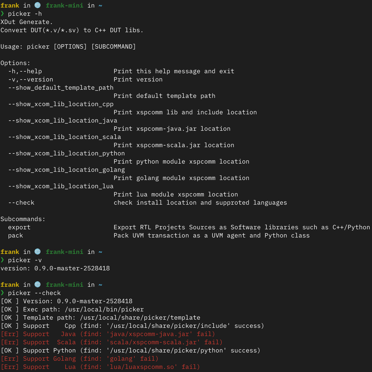
-h, --help: Prints the help info and exits. This is the top choice for understanding basic usage of Picker.
-v, --version: Displays Picker’s version number. It is very useful when reporting issues or confirming compatibility.
--check: Checks the installation paths and supported languages. This option helps you verify the installation status of Picker and all languages supported by the current environment.
Path Query Options
The following options are used to query various path information related to Picker, which is extremely useful for custom development and debugging:
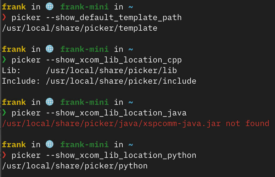
--show_default_template_path: Displays the default template path. When you need to customize the template for generated code, this option helps you locate the original template files.
--show_xcom_lib_location_cpp: Displays the location of the C++ version xspcomm libraries and header files. Used when manually integrating C++ projects.
--show_xcom_lib_location_java: Displays the location of the Java version xspcomm-java.jar. Required when using Picker-generated code in a Java project.
--show_xcom_lib_location_scala: Displays the location of the Scala version xspcomm-scala.jar. Used for Scala project integration.
--show_xcom_lib_location_python: Displays the location of the Python module xspcomm. Very helpful when used in a custom Python environment.
--show_xcom_lib_location_golang: Displays the location of the Go language module xspcomm. Used for Go project integration.
--show_xcom_lib_location_lua: Displays the location of the Lua module xspcomm. Required when using Picker-generated code in a Lua environment.
export Subcommand Common Arguments
export is the most commonly used subcommand, used to generate DUT interfaces. Here is a detailed explanation of its key parameters:
Required Arguments
file: Specifies the top-level DUT. .v/.sv source files point, must contain the top-level module. This is the only mandatory argument.
Input File-related Arguments
--fs, --filelist: Specifies the list of .v/.sv source files for the DUT. They can be separated by commas or using a .txt file (one RTL file path per line). Exceedingly useful when a design includes multiple files.
--sname, --source_module_name: Specifies the name of the RTL module to process. By default, Picker chooses the last module in the file marked with -f as the top-level module.
--internal: Path to the exported internal signals layout configuration file. Empty by default, indicating that internal pins are not exported. Used when access to the DUT’s internal signals is required.
Output Control Arguments
--lang, --language: The target project building language, defaults to python. Supported options include python/cpp/java/scala/golang/lua.
--tname, --target_module_name: Sets the module and file name for the generated target DUT wrapper. Defaults to the same name as the source module. For example, using --tname top will generate UTtop.cpp and UTtop.hpp files containing the UTtop class.
--tdir, --target_dir: Target directory for all exported outputs. If ends with ‘/’ or empty, the directory named after the target module name is created.
--sim: Selects the simulator, supports vcs or verilator. Defaults to verilator.
--e, --example: Whether to build an example project, defaults to OFF. Enabling this creates basic usage examples.
--autobuild: Whether to automatically build the generated project, defaults to true. Setting it to false can generate files without compiling.
Simulation Capability Arguments
--w, --wave_file_name: Waveform filename, empty means no waveform export. Specifying a filename will enable waveform dumping.
--c, --coverage: Whether to enable coverage collection, defaults to OFF. Upon enabling, coverage reports can be generated.
--checkpoints: Whether to enable save/restore functionality, defaults to OFF. Enabling allows capturing and restoring simulated state.
--vpi: Whether to enable VPI (used for flexible access to internal signals), defaults to OFF. VPI provides more flexible signal probing.
--F, --frequency: Sets the DUT frequency for VCS only, defaults to 100MHz. Units can be Hz/KHz/MHz/GHz.
Compilation Option Arguments
-V, --vflag: User-defined compilation parameters passed directly to the simulator compiler. E.g., -V '-x-assign;fast;-Wall;--trace'.
-C, --cflag: User-defined gcc/clang compilation directives, forwarded to compiler driver. E.g., -C '-O3;-std;c++17;-I./include'.
--verbose: Whether to enable verbose output mode, defaults to OFF. Details and debugging outputs are exposed.
Exercise
The exercises for this lecture have been published in the novice tasks. Please check the Learning Task 1: Picker section.